
Austria - 1939
|
|
VE 301 dyn - Radione Austria - 1939 |
|
|
|
 |
Italiano Restauro |
|||
|
|
|||||
 |
 |
 |
 |
||
|
|
|||||
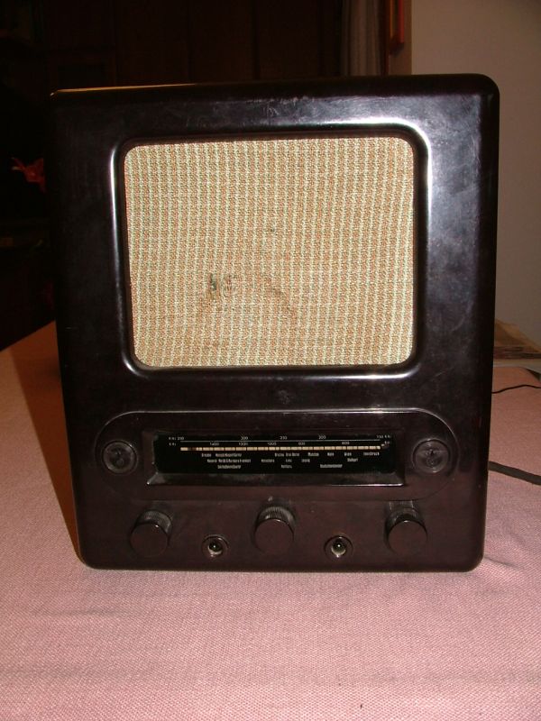
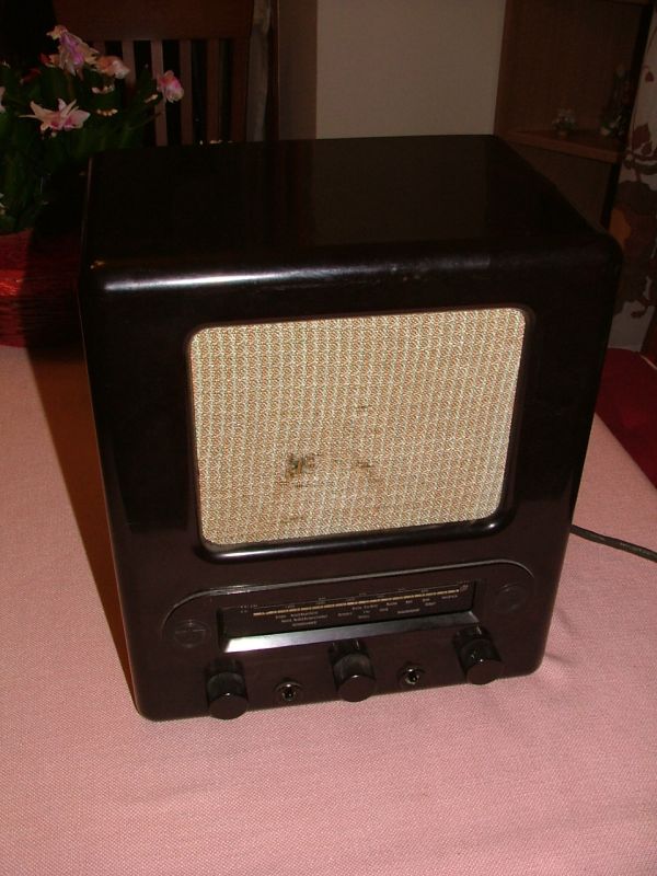
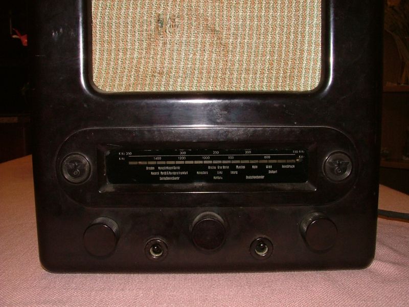
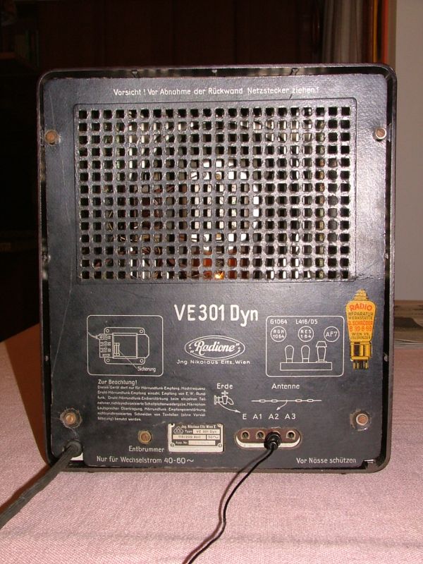
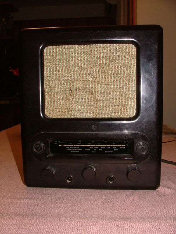
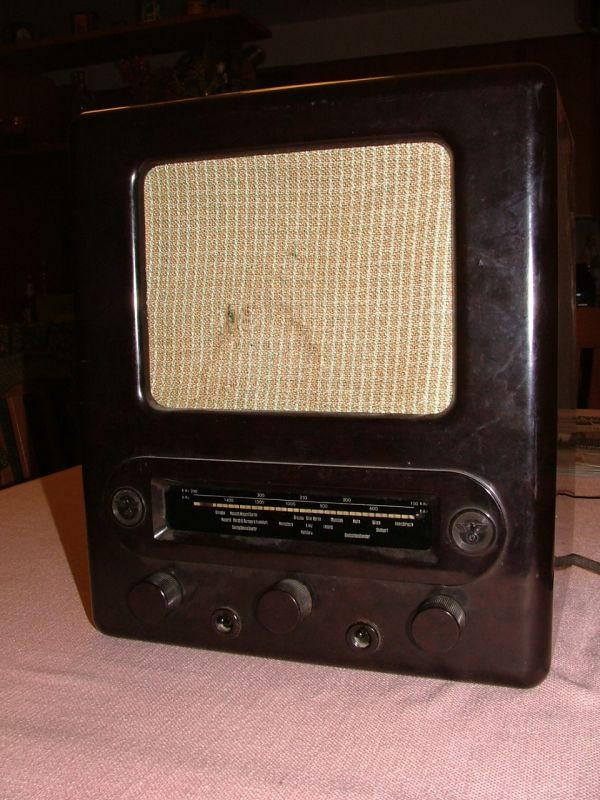
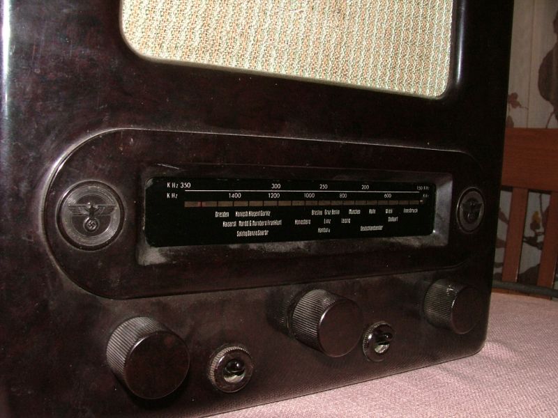
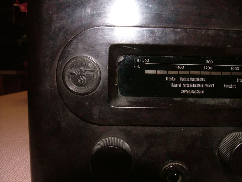
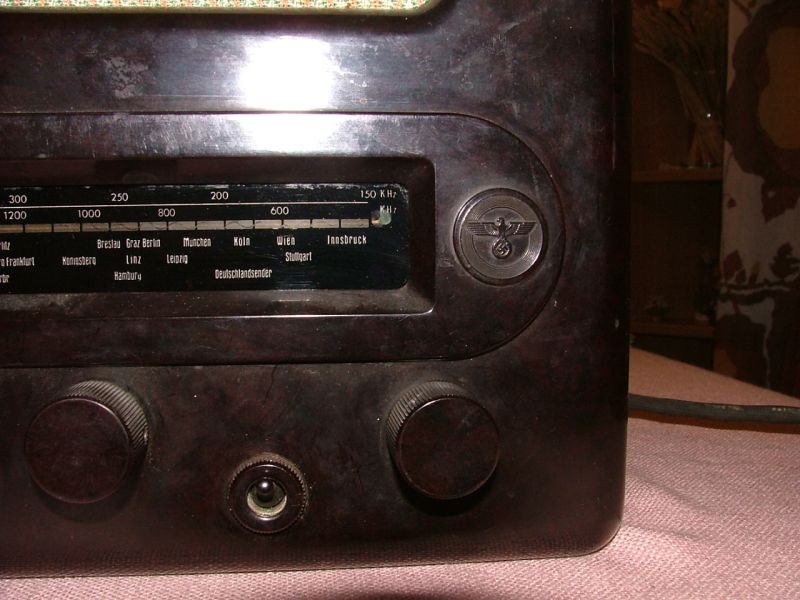
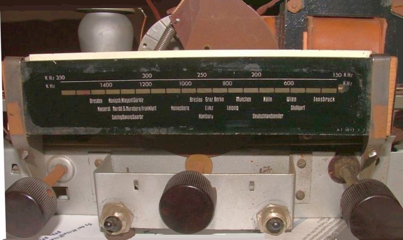
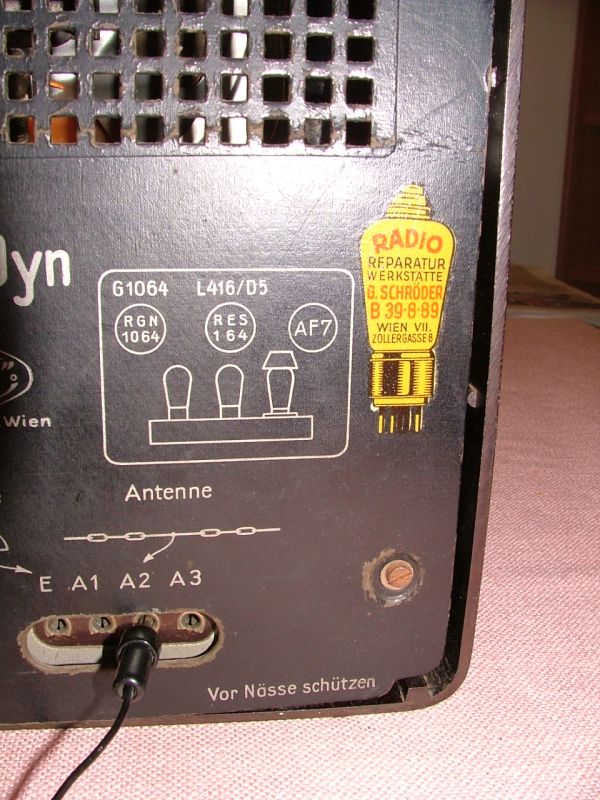
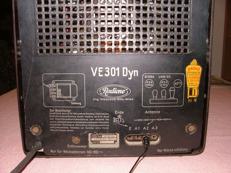
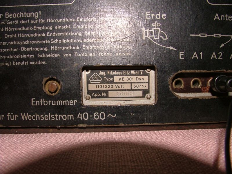
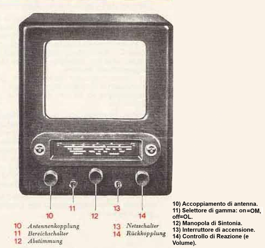
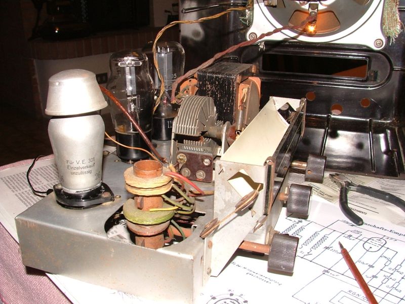
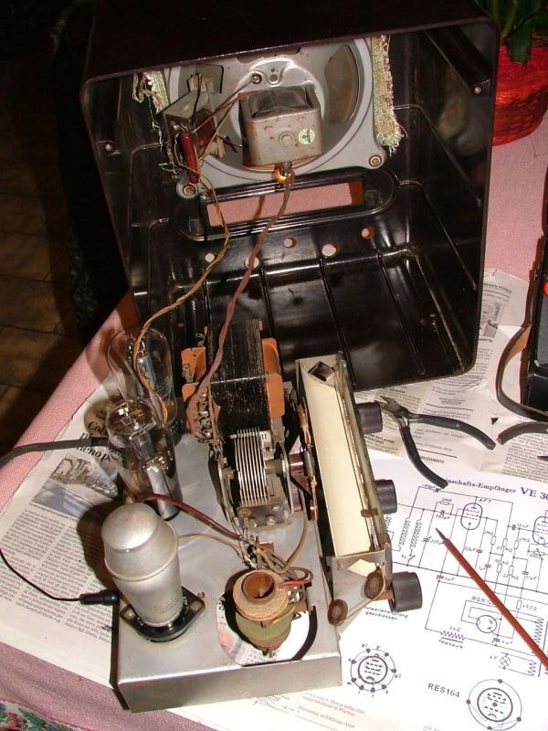
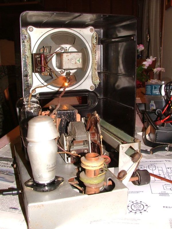
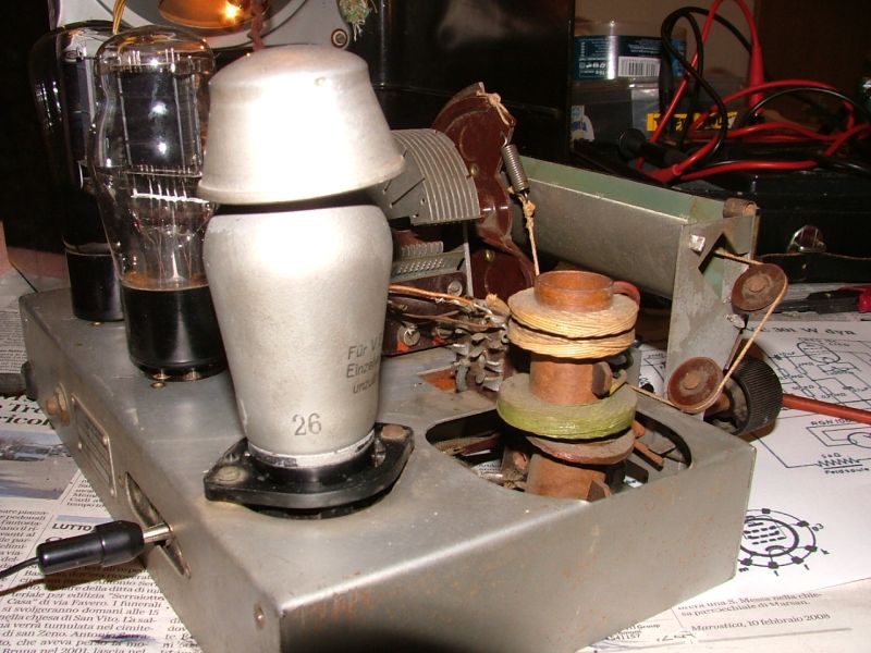
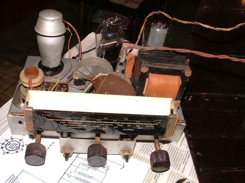
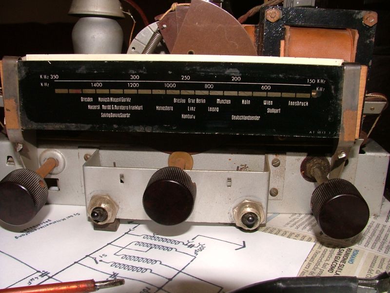
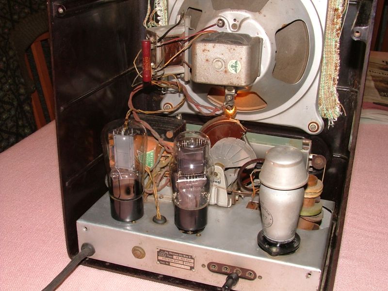
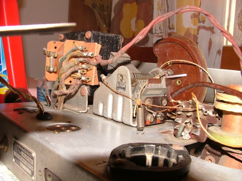
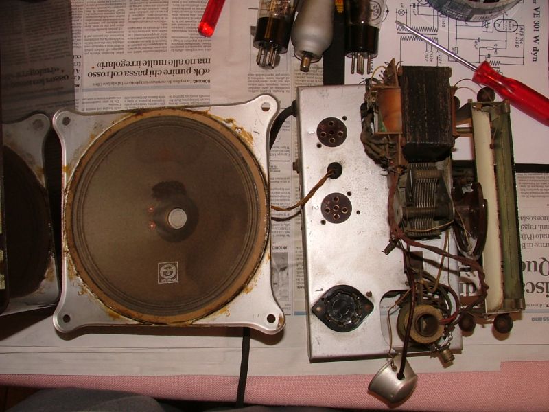
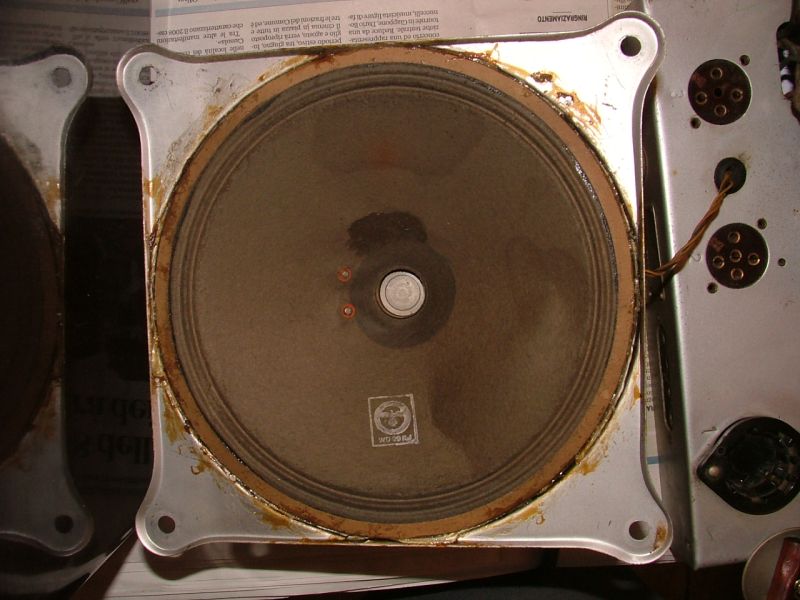
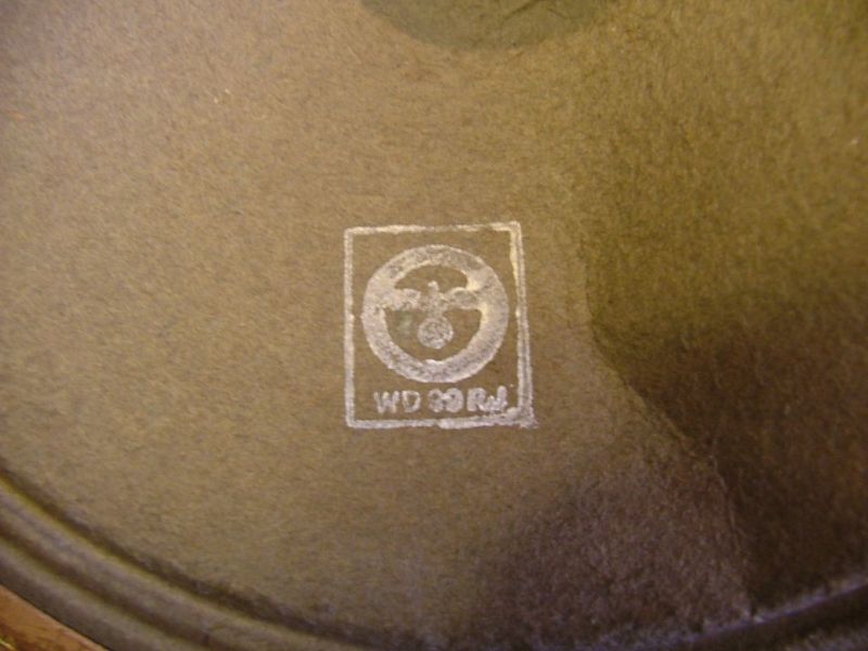
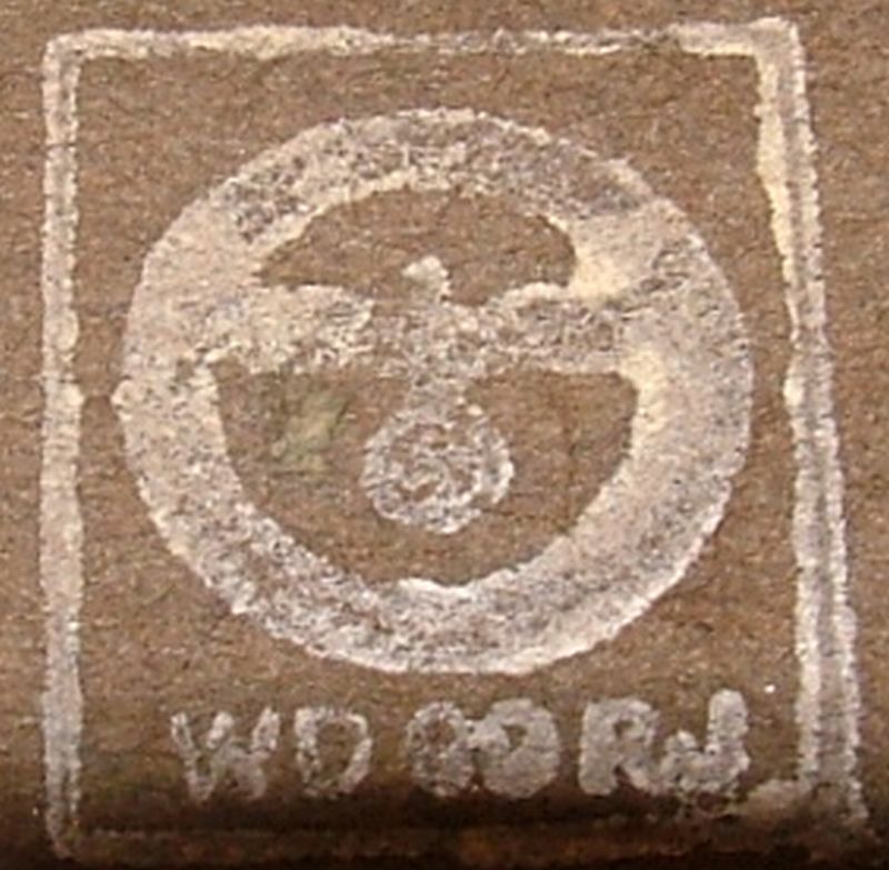
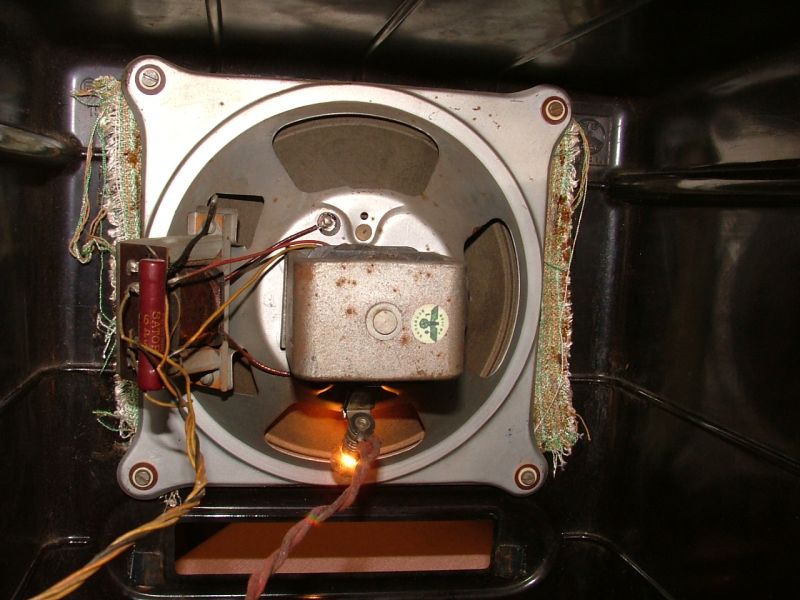
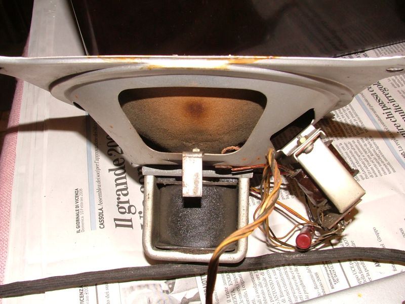
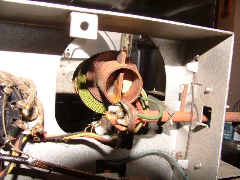
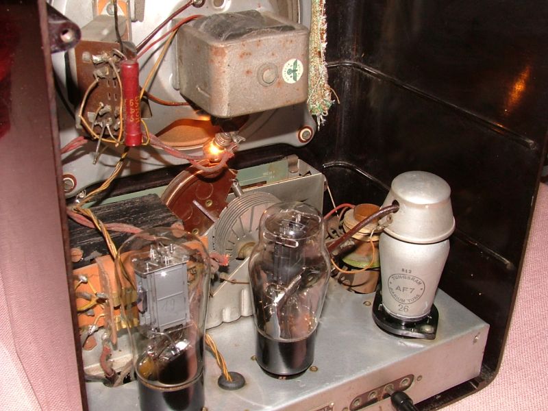
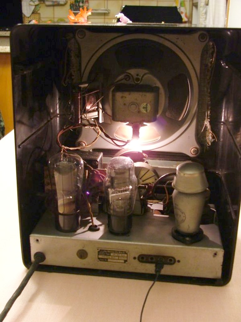
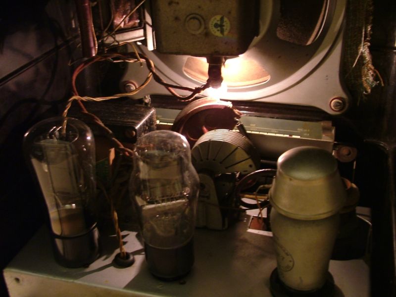
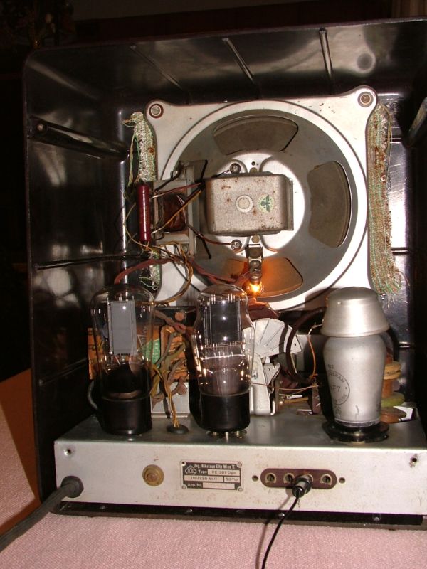
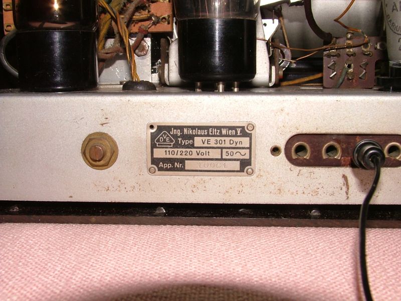
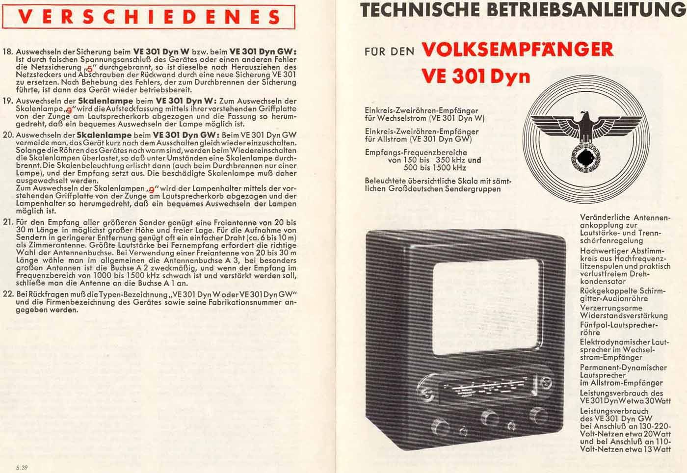
Questo Volks-Empfangër (ricevitore popolare) siglato VE301 (30 Gennaio 1931) per ricordare l'anno e il mese di nascita del III Reich, fu costruito dalla fabbrica Radione in Vienna alla fine degli anni 30. Nel marzo 1938 era avvenuta l'annessione dell' Austria al III Reich (Anschluss). L'Austria per legge non era più uno stato sovrano, dal 1938 era diventato un Land (una Regione) dell'impero tedesco. Tra molti altri cambiamenti, anche le industrie di elettronica austriache dovettero adeguarsi alle leggi tedesche e iniziare a produrre i ricevitori radio popolari voluti dal regime nazista. Come negli altri Volks-Empfangër, il circuito della VE301dyn era sempre del tipo a reazione, con ricezione delle Onde Medie (500-1500 kHz) e delle Onde Lunghe (150-350 kHz), e utilizzava tre valvole: una AF7 (un pentodo a Radio frequenza), una RES164 (un pentodo di potenza a frequenza audio) e una RGN1064 (rettificatrice a doppia semionda). I componenti utilizzati nella radio erano però più moderni rispetti alla 301 di inizio anni '30. Come valvola amplificatrice a Radio Frequenza veniva utilizzato un pentodo anziché un diodo, e l'altoparlante a spillo era stato sostituito da un elettrodinamico con bobina mobile che assicurava una risposta con maggiore fedeltà alle basse frequenze. Inoltre la scala parlante era del tipo lineare con l'asticella mossa da una funicella che scorreva su pulegge. Tutti i principali componenti della radio erano marcati con l'aquila nazista come si può vedere sulle foto del mobile e dell'altoparlante, il quale era del tipo elettrodinamico con l'avvolgimento che oltre a creare il campo magnetico lavorava anche da impedenza di filtro per la tensione anodica. I comandi per far funzionare la VE301dyn erano tutti raccolti sul pannello frontale sotto la scala di sintonia. Da sinistra a destra i comandi erano i seguenti: la manopola che azionava il variometro per l'accoppiamento d'antenna, seguiva l'interruttore-selettore di gamma: on per le Onde medie e off per le Onde lunghe; la manopola centrale era quella della sintonia, più avanti c'era l'interruttore di accensione e a destra il controllo di reazione che regolava anche il volume. Lo chassis della VE301dyn era in ferro, il mobile era realizzato in bakelite e nel pannello posteriore in cartone pressato c'erano aperture che davano accesso alle prese di antenna e di terra e permettevano il passaggio del cavo di alimentazione via rete elettrica, con fusibile da 0.5A e cambio tensione 110-130-220 Vac. Le dimensioni del mobile erano: 27,3 x 32 x 19 cm. Nota: l'immagine della valvola gialla incollata sulla destra del pannello posteriore era il contrassegno pubblicitario lasciato dal laboratorio di riparazioni radio G.Schröder situato in via Zollergasse 8, nel 7° distretto di Vienna, Austria, dove evidentemente la radio era stata portata a riparare. © IK3HIA, 2007 - 2025 (♣ Articolo di IK3HIA su Antique Radio Magazine N° 34 - 12/1999) |
|||||
|
|
|||||
 |
 |
|
|
||
 |
 |
 |
 |
||
 |
 |
|
 |
||
|
This Volks-Empfangër (people's receiver) signed 301 (January 30, 1931) to commemorate the year and month of the birth of the Third Reich, was built by the Radione factory in Vienna in the late 1930s. In March 1938, Austria was annexed to the Third Reich (Anschluss). By law, Austria was no longer a sovereign state, since 1938 it had become a Land (a Region) of the 3rd German Empire. Among many other changes, the Austrian electronics industries also had to adapt to German laws and begin producing the popular radio receivers desired by the Nazi regime. As in the other Volks-Empfangër, the circuit of the VE301dyn was always of the reaction type, with reception of Medium Waves and Long Waves, and used three valves: an AF7 a Radio frequency pentode, a RES164 an audio frequency power pentode and an RGN1064, a double half-wave rectifier. All the main components of the radio were marked with the Nazi eagle as can be seen in the photos of the cabinet and the speaker, which was of the electrodynamic type with the winding that in addition to creating the magnetic field also worked as a filter impedance for the anode voltage. The components used in the radio were more modern than the 301 of the early 1930s. A pentode was used as the RF amplifying valve instead of a diode, and the pin speaker had been replaced by an electrodynamic one with a moving coil that ensured a more faithful response at low frequencies. Furthermore, the dial was of the linear type with the rod moved by a cord that ran on pulleys. The controls to operate the VE301dyn were all collected on the front panel under the tuning scale. From left to right the controls were the following: the knob that operated the variometer for antenna coupling, followed by the range selector switch: on for Medium Waves and off for Long Waves; the central knob was the tuning knob, further forward was the power switch and on the right the reaction control that also adjusted the volume. The chassis of the VE301dyn was made of iron, the cabinet was made of bakelite and in the back panel in pressed cardboard there were openings that gave access to the antenna and ground sockets and allowed the passage of the of the power cable via electrical network, with a 0.5A fuse and voltage change 110 - 130 - 220 Vac. The cabinet dimensions were: 10.7 x 12.6 x 7.5 inch. Note: the image of the yellow valve glued to the right of the rear panel was the advertising sign left by the G.Schröder radio repair shop located at Zollergasse 8, in the 7th district of Vienna, Austria, where the radio had evidently been taken for repairs. © IK3HIA, 2007 - 2025 (♣ IK3HIA's article on Antique Radio Magazine N° 34 - 12/1999) |
|||||
|
|
|||||
 |
 |
 |
 |
||
 |
 |
 |
 |
||
 |
 |
 |
 |
||
|
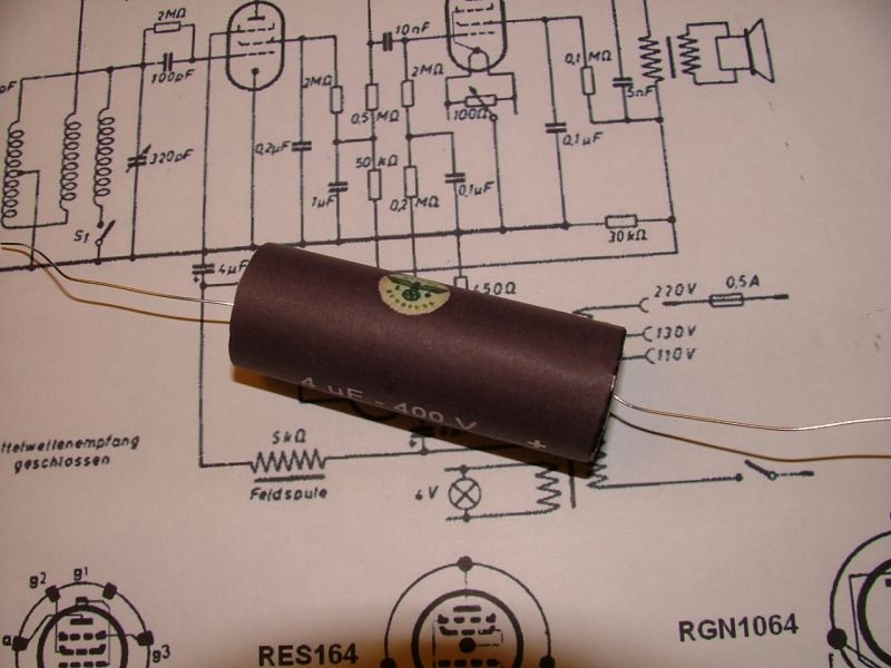
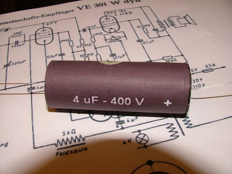
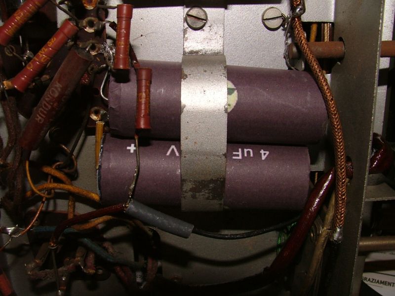
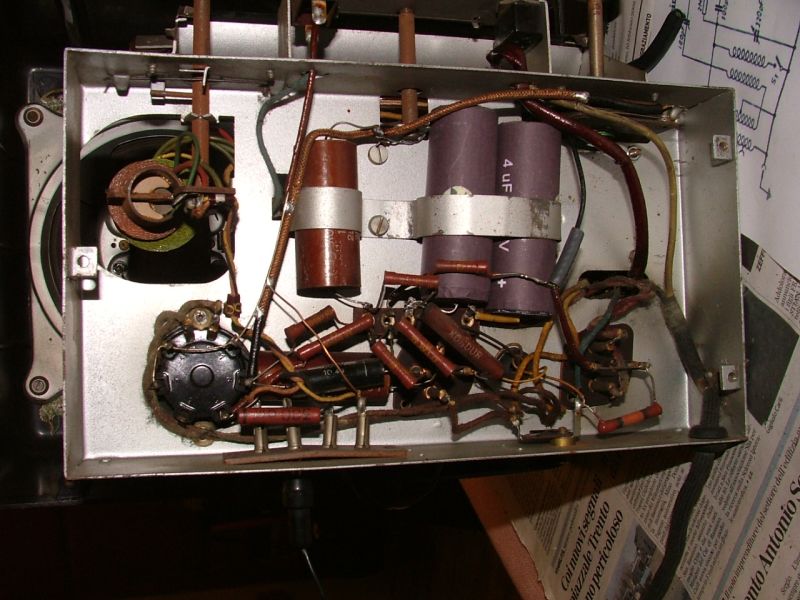
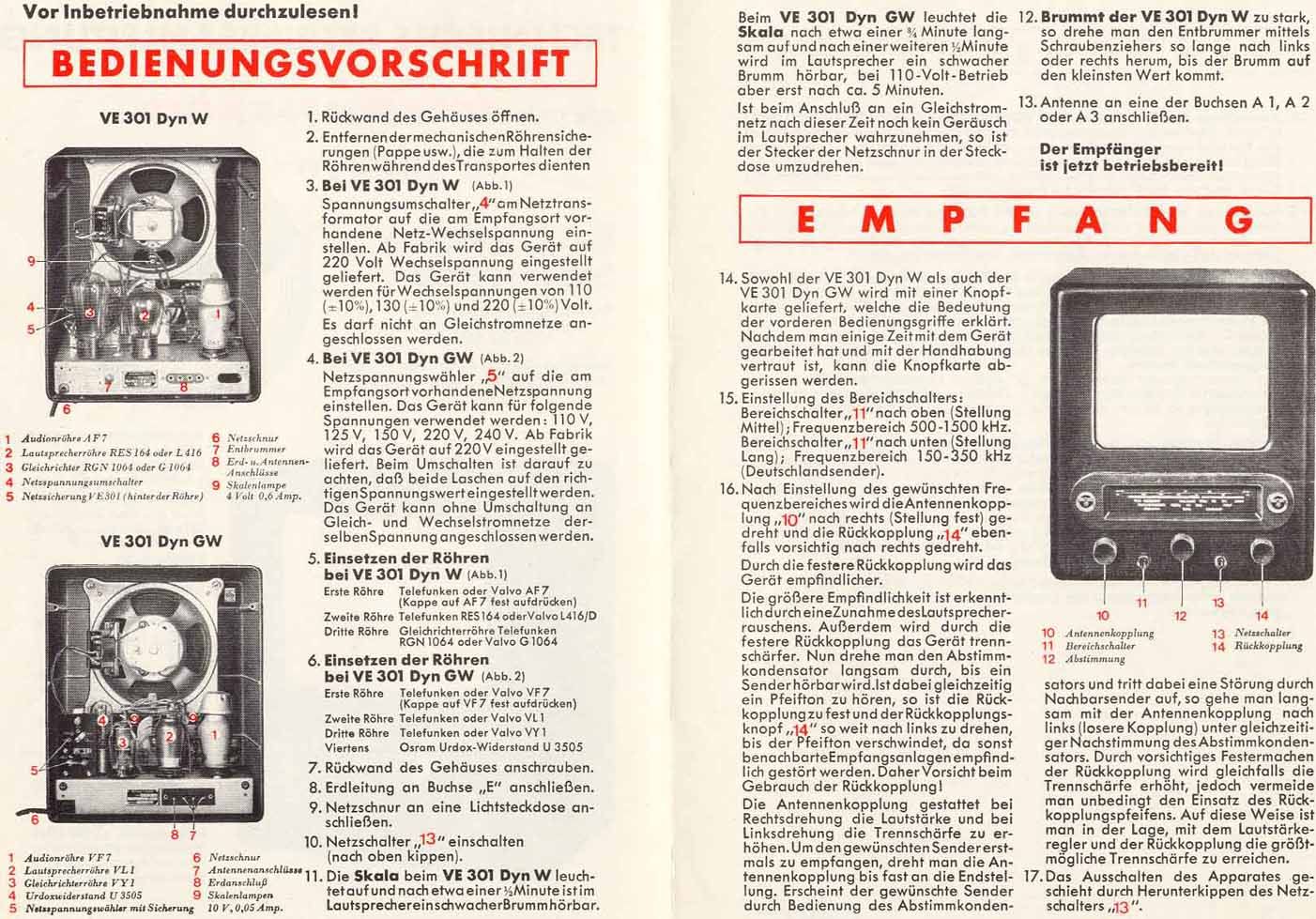
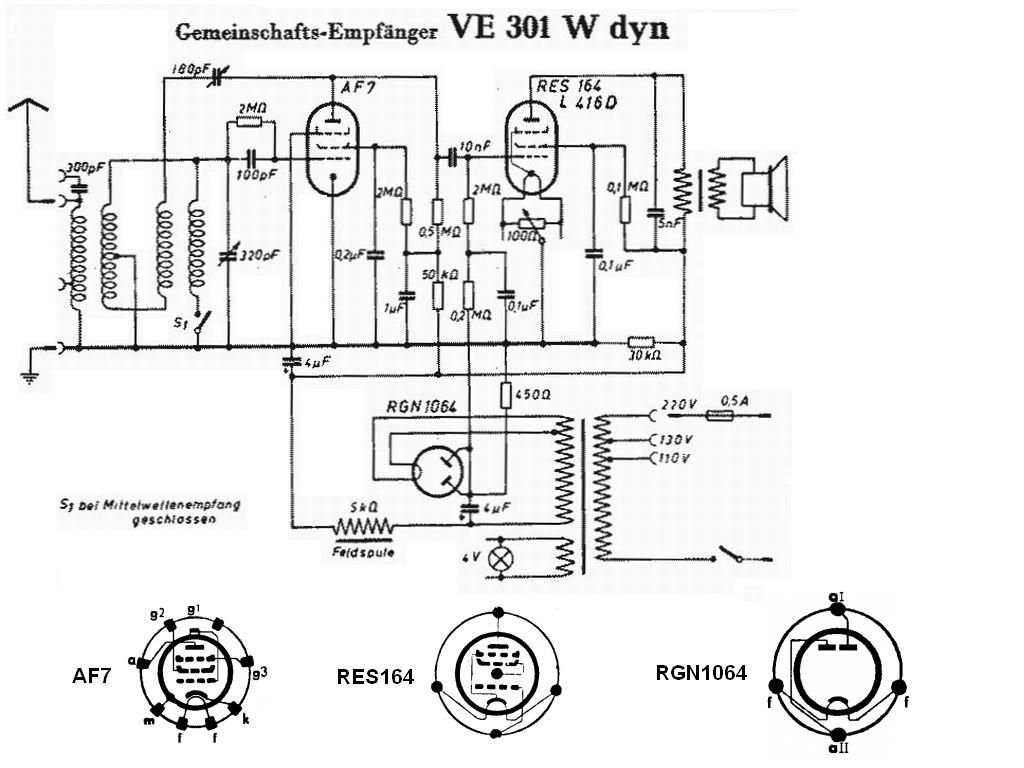
Per rimettere in funzione l'esemplare visibile nelle foto ho dovuto solamente sostituire i vecchi condensatori elettrolitici nettamente in perdita con due componenti moderni. Sono riuscito a realizzare i due condensatori utilizzando due tubetti ex medicinali di misura adeguata, in ciascuno dei tubetti hanno trovato posto due condensatori da 2,2 µF 250 V collegati in serie per un totale di 4,4 µF 500 VL. I tubetti li ho ricoperti incollandoci sopra due strisce di carta con colore e diciture simili alle originali che ho stampato con il computer. Dopo aver accesa la radio e aver controllato con il voltmetro la tensione anodica (340 Vcc misurati sull'avvolgimento di eccitazione dell'altoparlante) e quella dei filamenti (4 Vac sulla AF7, sulla RES164 e sulla RGN1064), ho collegato un'antenna a dipolo tra le prese E e A1 e ho potuto sintonizzare alcune stazioni in Onde Medie. Regolando con cura il trimmer da 100 Ohm (comando a vite sul pannello posteriore a sinistra dell'etichetta con la matricola) posto in parallelo al filamento della RES164 si può tentare di ridurre il ronzio residuo causato dai 50 Hz della rete. Tra le immagini seguenti più in basso si possono scaricare il manuale d'uso originale della radio e lo schema elettrico. © IK3HIA, 2007 - 2025 |
|||||
 |
 |
 |
 |
||
 |
 |
 |
 |
||
|
To get the specimen visible in the photos working again, I only had to replace the old electrolytic capacitors that were clearly losing power with two modern components. I managed to make the two capacitors using two ex-medicine tubes of adequate size, each tube contained two 2.2 µF 250 V capacitors connected in series for a total of 4.4 µF 500 VL. I covered the tubes by gluing two strips of paper on top with similar color and wording to the originals that I printed with the computer. In the following images you can download the original user manual of the radio and the wiring diagram. © IK3HIA, 2007 - 2025 |
|||||
 |
 |
 |
 |
||
 |
 |
|
 |
||
|
Return to top of page
|
|||||
| Return to: Vecchie Radio | Back to: Volksradioempfängeren page |