 |
Bush TR82D
- early model United Kingdom - 1962 |
|
|
|
Bush TR82D
- early model United Kingdom - 1962 |
|
 Description
Restoration
Description
Restoration |
 |
 Descrizione
Restauro
Descrizione
Restauro |
|
|
Click sulle immagini per
ingrandire
|
|||
 |
 |
 |
 |
|
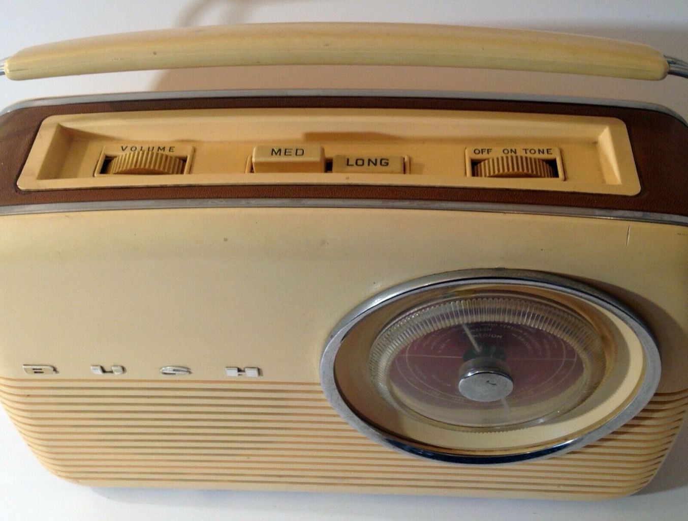
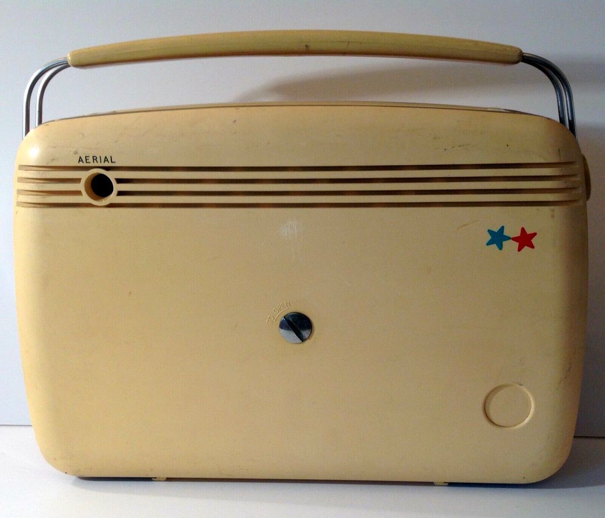
Bush TR82D - Bush Radio,
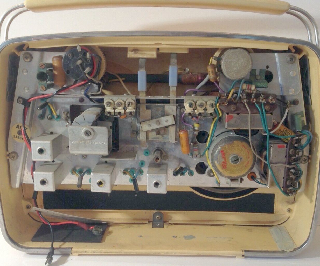
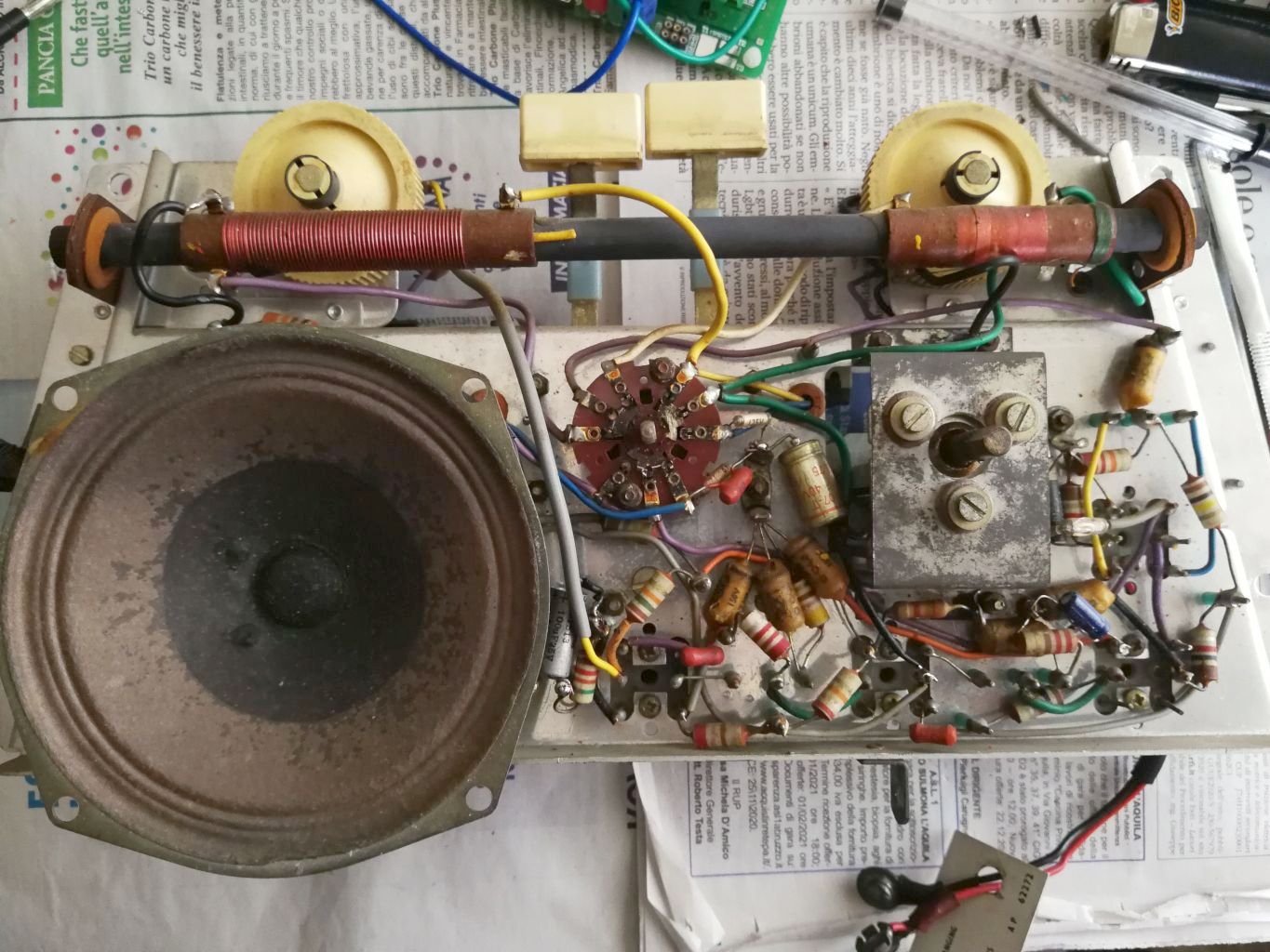
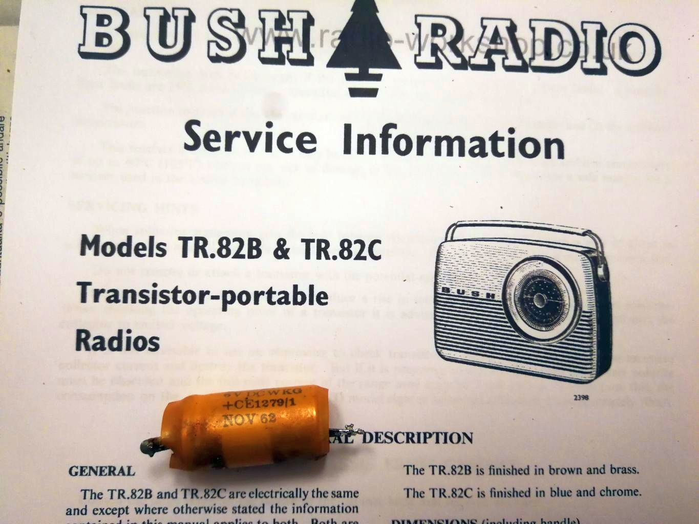
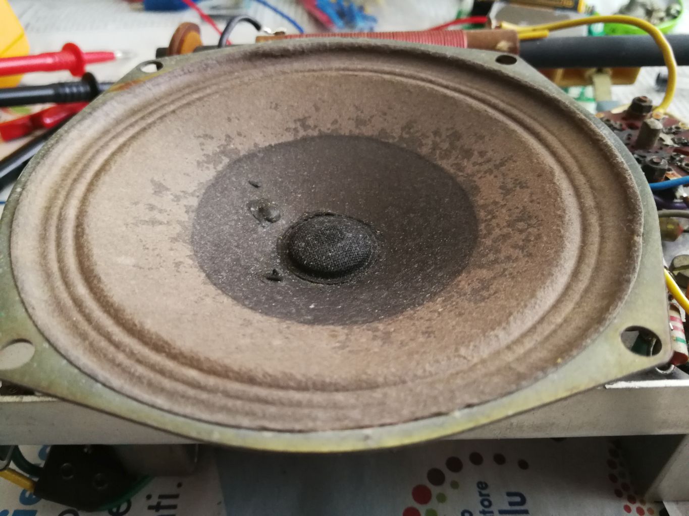
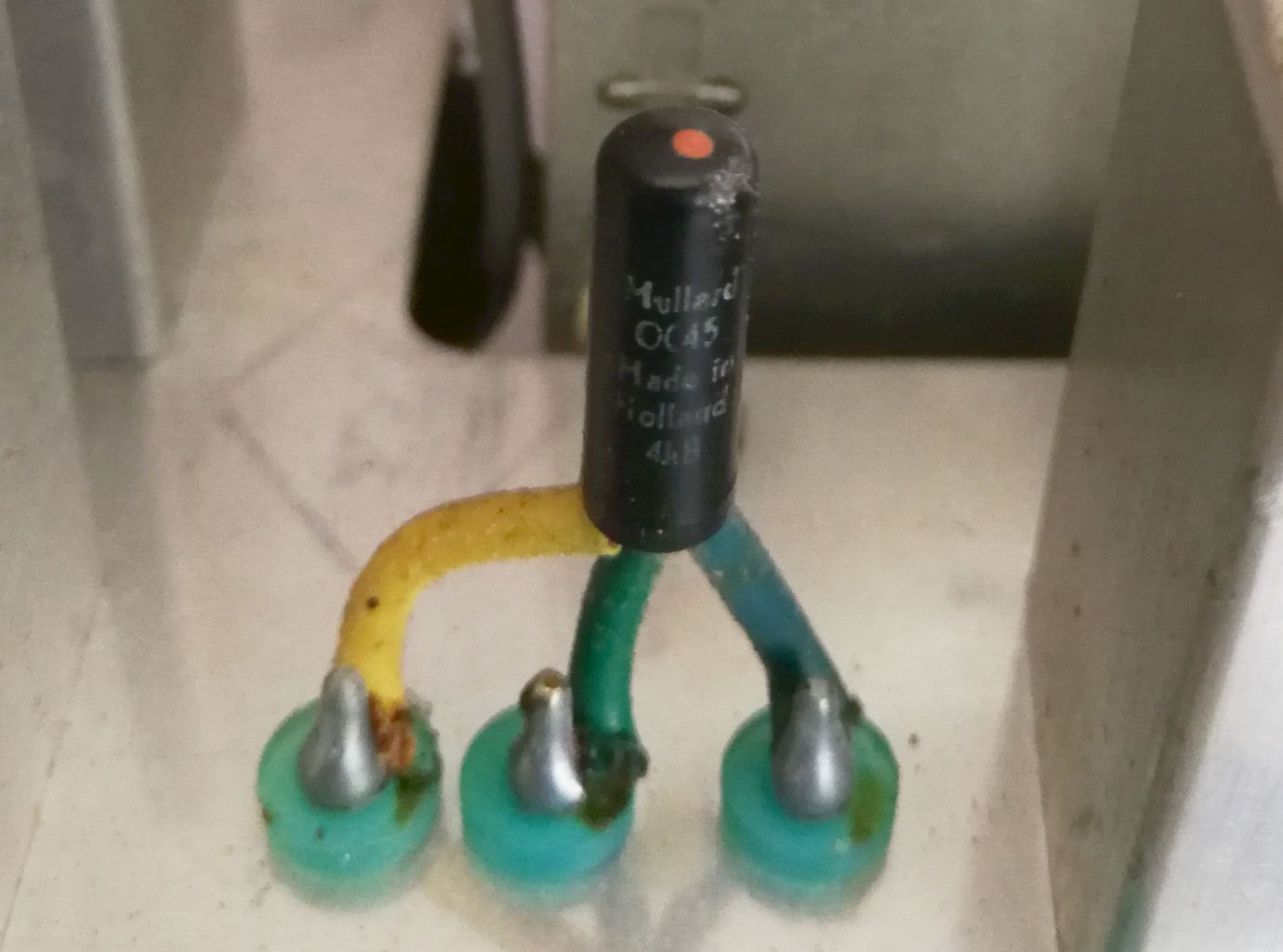
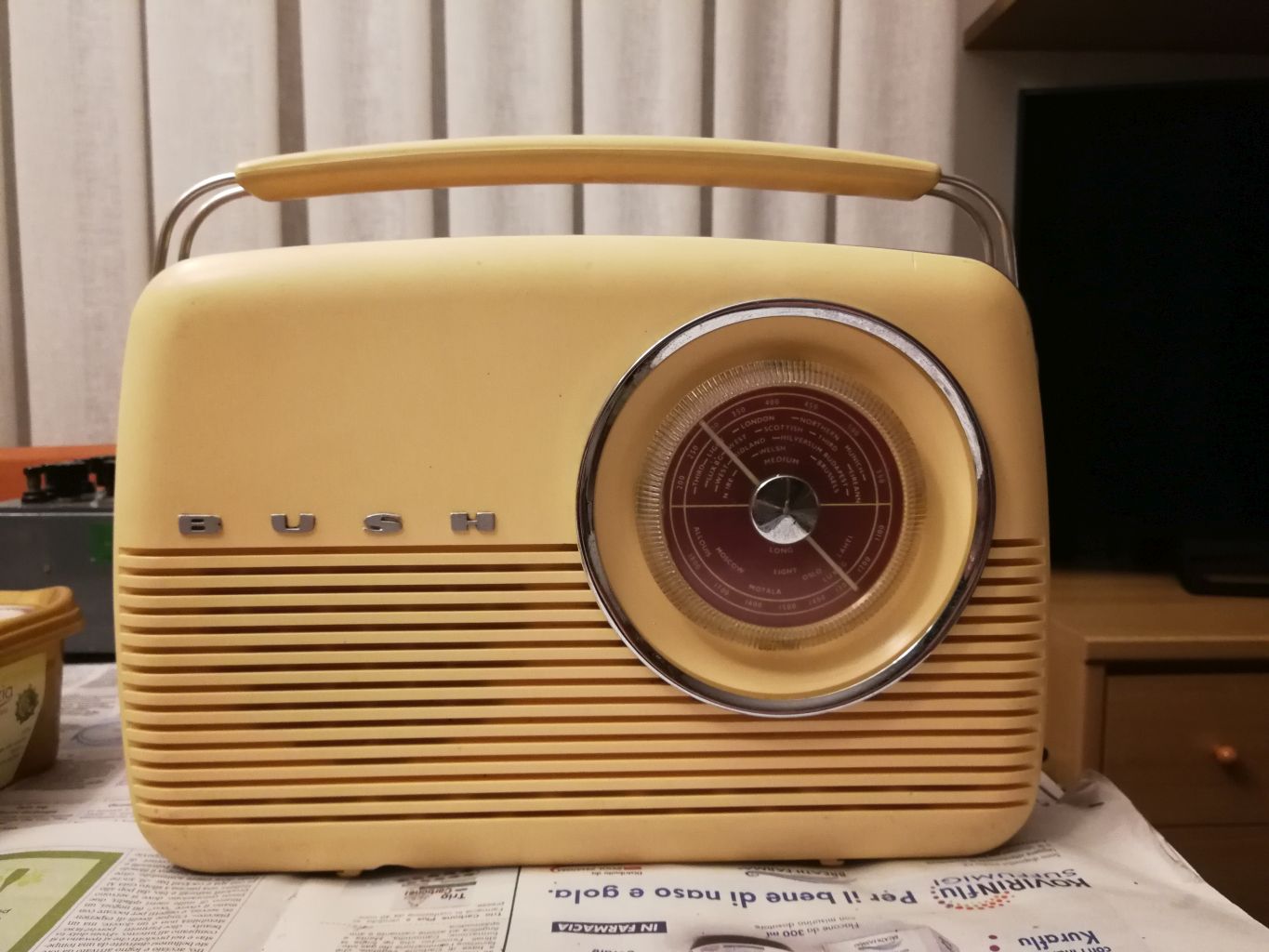
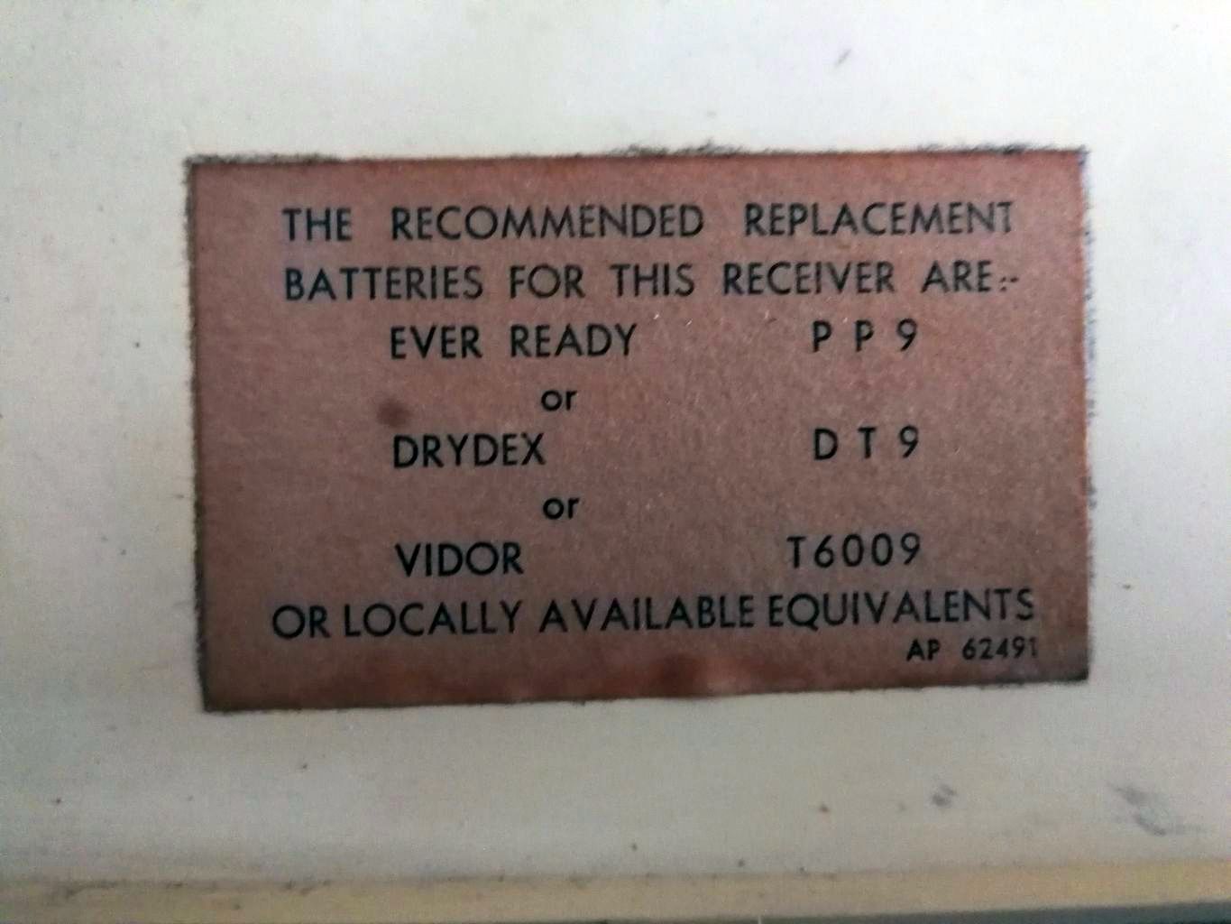
London - U.K. - 1962 The English Bush company began manufacturing and marketing the TR82 transistor radios series in 1959. The plastic cabinet design was designed by David Ogle in the mid 1950s and it was used by Bush in a series of portable tube radios. Following the development and the production in the U.S.A. of the first transistors by Texas Instruments, from 1954 in the United States also began the production of portable radios that used the new solid state components. In the UK it was the Mullard Limited that began manufacturing transistors with his OC series, and Bush also began using semiconductors in its portable radios. The first Bush transistor radio came out in 1959, it was a rather bulky portable radio becouse it used the chassis and the cabinet of the previous tube series. The largee size of the TR82 did not seem to determine a disadvantage indeed, thanks to the good sensitivity, the good acoustic performance of the Celestion loudspeaker used, and thanks to modern and pleasant aesthetics, the Bush radio achieved great market success. This success was renewed in 1997 when the Bush Radio of London put on the market a replica of the TR82 / 97 model including the FM band, which kept the same rounded vintage design of the sixties. The copy in my possession is a TR82D first series built in 1962, which uses an A177 chassis and the transistors Mullard OC44, OC45, OC45, OC71, OC78D, OC78, OC78. The model D differs from the model C as it is characterized by some aesthetic embellishment in the cabinet with the use of ivory plastic and a light brown band around it. Under the radio there is the label with the serial number showing the serial number: 508/07249, while on the right side of the rear cover there are two stars, one blue and one red. Power is supplied by a large 9V Eveready PP9 type battery or equivalent which is still easily found on the market. © IK3HIA 2020. |
|||
 |
 |
 |
 |
|
Back to the top of the page >>
|
|||
|
Bush TR82D - Bush Radio, Londra - Regno Unito - 1962 La ditta iglese Bush iniziò la costruzione e la commercializzazione delle radio a transistor della serie TR82 nel 1959. Il design del mobile in plastica era stato progettato da David Ogle a metà degli anni 50 e fu utilizzato dalla Bush in una serie di radio portatili a valvole. A seguito dello sviluppo e della produzione negli U.S.A. dei primi transistori da parte della Texas Instruments, dal 1954 negli Stati Uniti iniziò la produzione anche di radio portatili che utilizzavano i nuovi componenti a stato solido. Nel Regno Unito fu la Mullard a iniziare la produzione di transistor con la serie OC, e anche la Bush iniziò a impiegare i semiconduttori nelle sue radio portatili. La prima radio Bush a transistor uscì nel 1959, era una radio portatile piuttosto ingombrante perché utilizzava lo chassis e il mobile della precedente serie a valvole. L'ingombro notevole della TR82 non sembrò determinare uno svantaggio anzi, per merito della buona sensibilità, dell'ottima resa acustica dell'altoparlante Celestion utilizzato, e grazie all'estetica moderna e piacevole, la radio Bush ottenne un grosso successo di mercato. Successo che si rinnovò nel 1997 quando la Bush Radio di Londra pose in commercio una replica del modello TR82/97 che includeva la gamma FM, il quale manteneva lo stesso design arrotondato stile vintage degli anni sessanta. L'esemplare in mio possesso è un TR82D prima serie costruito nel 1962, che utilizza uno chassis A177 e la serie di transistor OC44, OC45, OC45, OC71, OC78D, OC78, OC78. Il modello D si diversifica dal modello C in quanto è caratterizzato da qualche abbellimento estetico del mobile con l'utilizzo di plastica color avorio e di una fascia color marrone chiaro attorno. Sotto la radio c'è l'etichetta con la matricola che riporta il numero seriale: 508/07249, mentre sul lato destro del coperchio posteriore sono impresse due stelle, una azzurra e una rossa. L'alimentazione è fornita da una grossa batteria da 9V tipo Eveready PP9 o equivalente che è ancora facilmente rintracciabile sul mercato. © IK3HIA 2020. |
|||
 |
 |
 |
 |
|
Back to the top of the page >>
|
|||
|
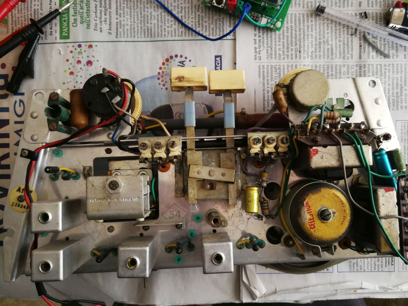
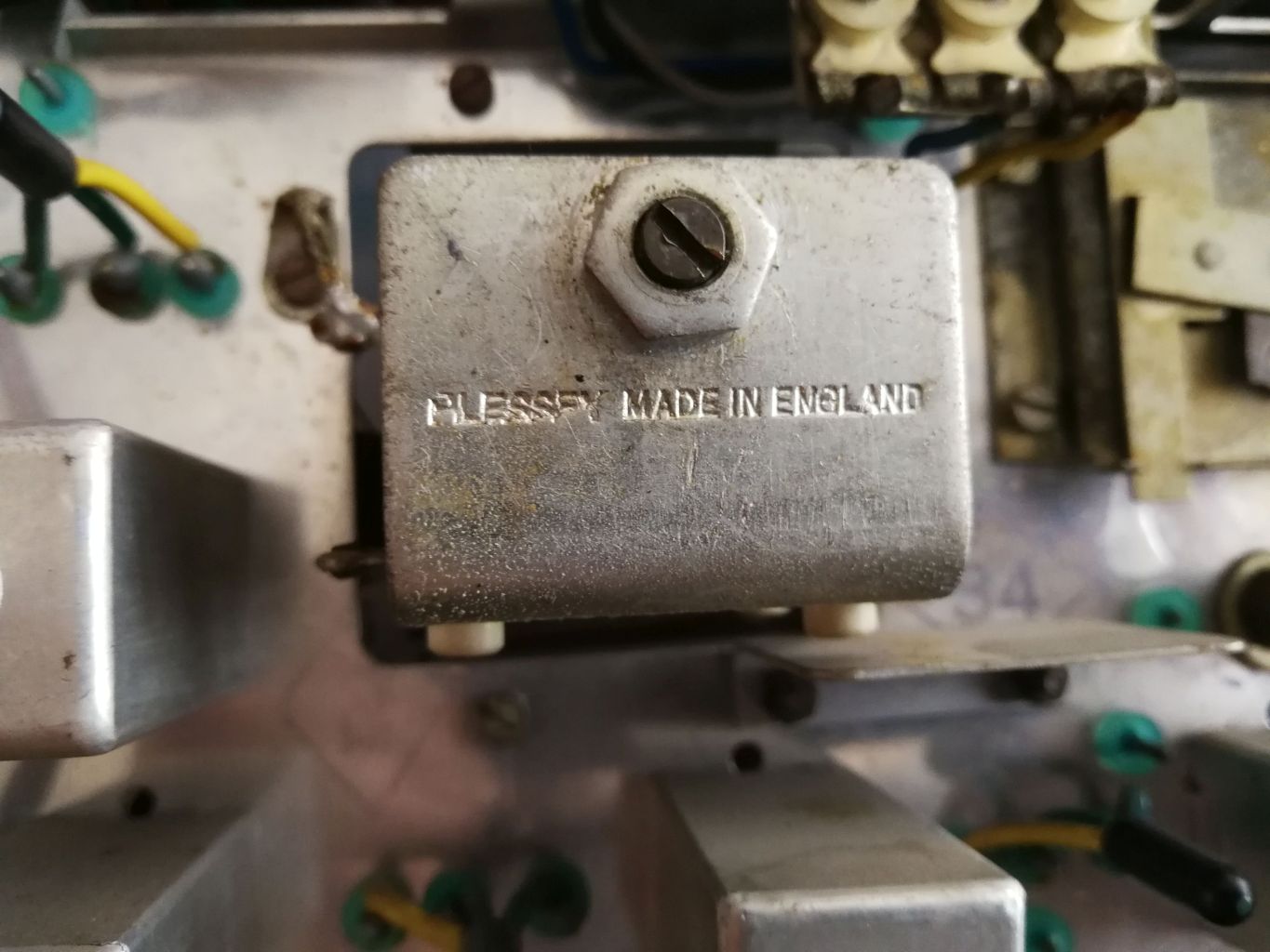
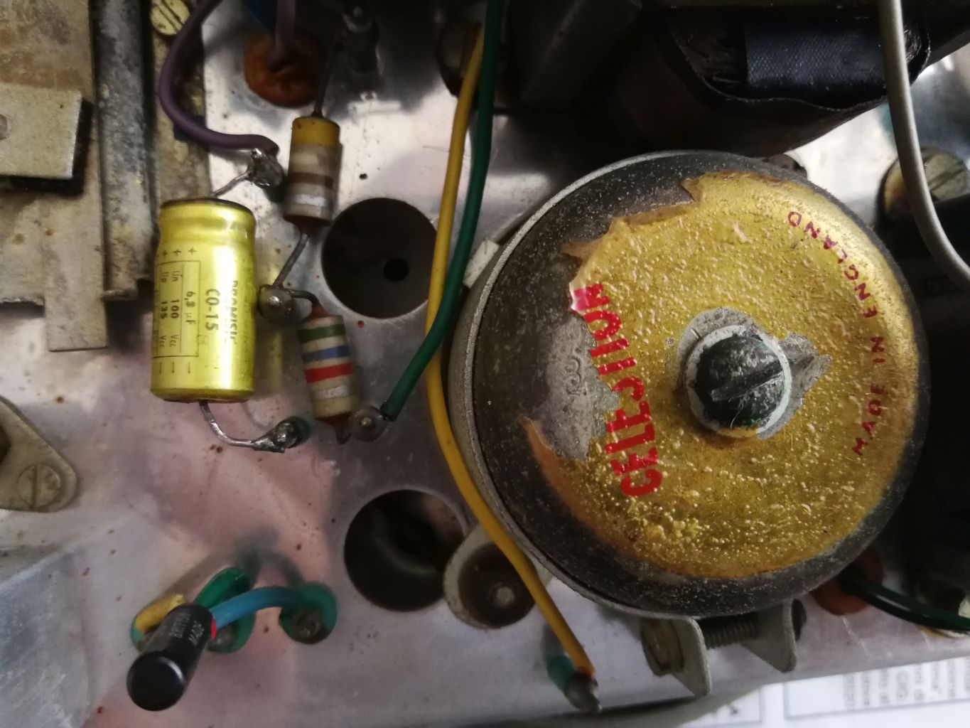
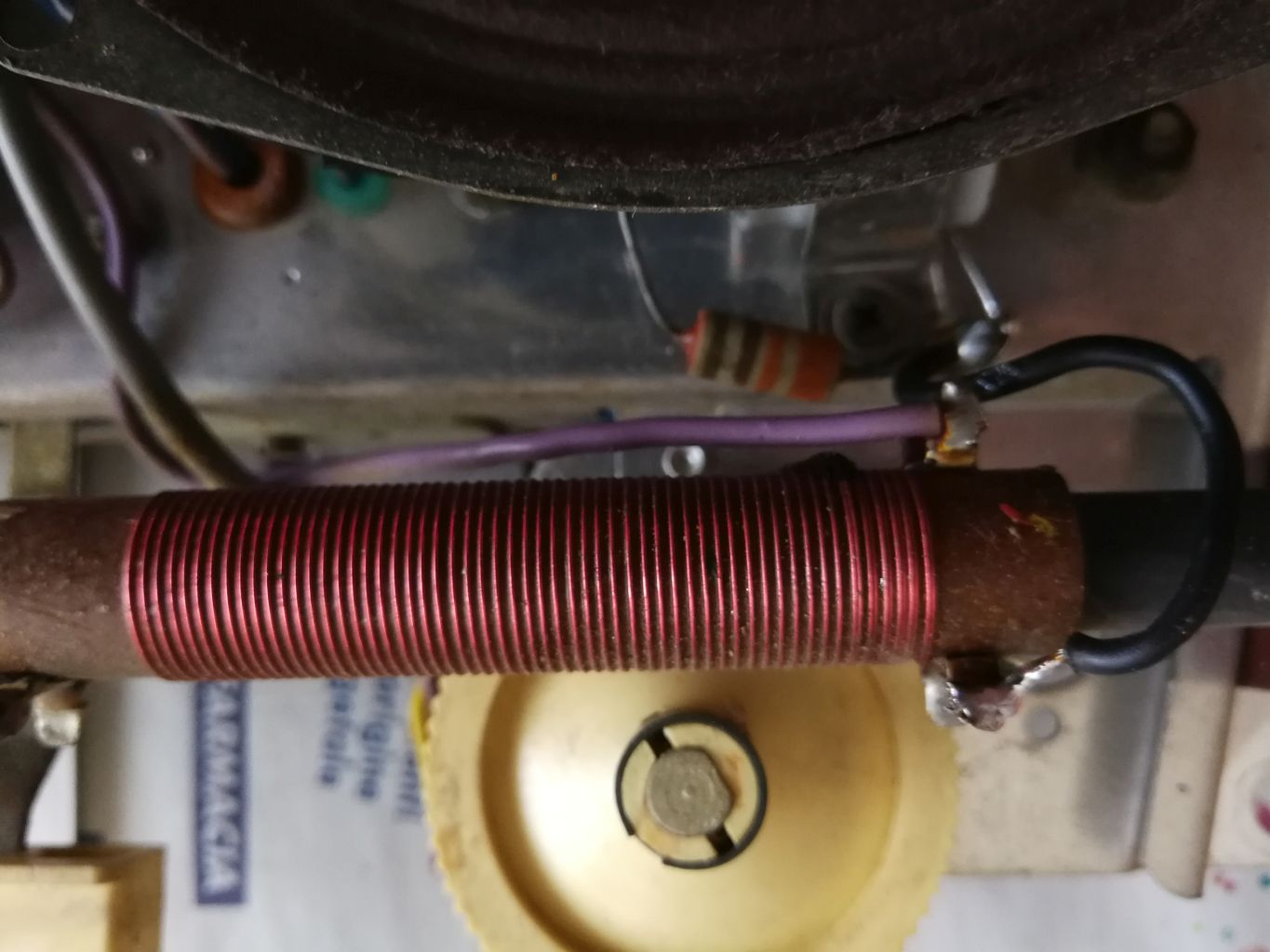
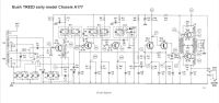
Restoration. Considering that the device was dated and to avoid toxic explosions and smokes I did not dare to immediately energize, but carefully I removed the large tuning knob, the scale index and I took off the four internal self-tapping screws, then I extracted the chassis from the case. After checking the appearance of the electrolytic capacitors and realizing that there was no need for any illusions, I replaced all six with more modern components of equal capacity found in my usual miracle drawer. I made the replacement after checking the "new" elements using of a capacitor / ESR meter and checking that the working voltage marked on the component was at least equal or more than 25 V. Always before powering the radio, I checked with the ohmmeter the continuity of the connection from the battery contacts to the radio circuit. By setting the power switch to ON, the positive pole marked continuity with the metal frame of the receiver. Instead, between the negative pole of the battery connector and the negative of the 100 MF C27 electrolytic capacitor I measured a few tens of Ohms. Bad luck! One of the ignition switch contacts, which is coaxial to the tone pot, was resistive and all attempts to reset it by tripping it multiple times have been unsuccessful. The most brilliant solution would have been to replace the item with a new one, but it would have been utopian to find an equal one. Other times I had solved similar problems on switch potentiometers by disassembling the entire component and spraying the deoxidizer spray component into it. Unfortunately, the potentiometer in question was hermetically built, with rivets that held the black plastic part against the metal body of the variable resistor. After a bit of lucubrations I solved the problem by practicing with a small drill and very carefully a 2 mm hole on one side of the plastic part, I brought the spray straw closer to the hole and I sprayed the flux a couple of times by activating more times the switch. Remeasuring with the ohmmeter the resistance was gone and now there was continuity between the negative pole and the radio circuit. Then I closed the hole with a piece of black insulating tape. While I was there I used the spray on both potentiometers trying to get the flux in from the small slots where the contacts come out, then I reserved the same treatment for the MW and LW range switch. At this point I connected a 9V power supply and ventured to apply voltage. To my relief I heard some hiss coming from the speaker and by rotating the pin of the variable capacitor I was able to tune some stations on the Medium Waves. All the old "first series" germanium transistors from Mullard were still working. Turning up the volume of the radio the output sound level increased but it was rather distorted. Could there be some other deteriorated capacitor? After the usual series of lucubrations I decided not to insist with the capacitors and rather to check the calibration of the medium frequency transformers. The Bush TR82 medium frequency is 470 kHz, so I adjusted the modulated oscillator to this value, I inserted the probe with the signal on the TR1 collector (OC44), I turned the radio on. The whistle with modulation came out of the speaker, so I started the calibration starting from the IFT1 transformer, then IFT2 and IFT3. By carefully adjusting the core of the IFT3, the tone level coming out of the speaker quadrupled. With exultation, I did the calibration a second time and at the end I unplugged my instruments. The radio is as if reborn, the signals on the medium wave have multiplied and the outgoing audio was loud and clear. With some cleaning wipes stolen from my XYL I cleaned the cabinet inside and the outside surfaces, then I reassembled everything. The restoration operation had been successful and to celebrate the event I enjoyed a good espresso while listening to the strong signal coming from the RTL station which broadcasts in long wave from France on 234 kHz. © IK3HIA 2020. |
|||
 |
 |
 |
 |
|
Back to the top of the page >>
|
|||
|
Restauro Considerando che l'apparecchio era piuttosto datato e per evitare scoppi e fumate tossiche non mi sono azzardato a dare subito tensione, ma sfilando con cautela la larga manopola di sintonia, l'indice della scala e togliendo le quattro viti autofilettanti interne ho estratto lo chassis dal mobile. Dopo avere controllato l'aspetto dei condensatori elettrolitici e capito che non era il caso di farsi illusioni, li ho sostituiti tutti e sei con componenti più moderni di uguale capacità trovati nel mio solito cassetto dei miracoli. La sostituzione l'ho effettuata previo controllo degli elementi "nuovi" tramite capacimetro/ESR meter e ho verificato che la tensione di lavoro fosse almeno di 25 V. Sempre prima di alimentare la radio ho controllato con l'ohmmetro la continuità del collegamento dai contatti della batteria al circuito della radio. Posizionando l'interruttore di accensione su ON, il polo positivo segnava continuità con il telaio metallico del ricevitore. Invece tra il polo negativo del connettore della batteria e il negativo del condensatore elettrolitico da 100 MF C27 ho misurato qualche decina di Ohm. Sfortuna! Era ovvio che uno dei contatti dell'interruttore di accensione, che è coassiale al potenziometro del tono, era resistivo e sono stati inutili tutti i tentativi di ripristinarlo facendolo scattare più volte. L'ideale sarebbe stato sostituire il componente con uno nuovo, ma sarebbe stata un'utopia sperare di trovarne uno uguale. Altre volte ero venuto a capo di problemi simili su potenziometri con interruttore smontando l'intero componente e spruzzandovi dentro il componente dello spray disossidante. Purtroppo il potenziometro in questione era costruito in modo ermetico, con rivetti che tenevano bloccata la parte in plastica nera contro il corpo metallico della resistenza variabile. Dopo un po' di elucubrazioni ho risolto il problema praticando con un trapanino e con molta cautela un forellino da 2 mm su un lato della parte in plastica, ho avvicinato al foro la cannuccia dello spray e ho spruzzato il disossidante un paio di volte azionando contemporaneamente l'interruttore. Rimisurando con l'ohmmetro la resistenza era sparita e adesso c'era continuità tra polo negativo e circuito della radio, e ho chiuso il forellino con un pezzetto di nastro isolante nero. Già che c'ero ho utilizzato lo spray su entrambi i potenziometri cercando di far entrare il disossidante dalle piccole fessure dove escono i contatti, poi ho riservato lo stesso trattamento al commutatore di gamma MW e LW. A questo punto ho collegato un alimentatore da 9 V e mi sono arrischiato a dare tensione. Con sollievo ho sentito del fruscio provenire dall'altoparlante e ruotando il perno del condensatore variabile ho potuto sintonizzare qualche stazione sulle Onde Medie. Tutti i vecchi transistor al germanio "prima serie" della Mullard erano ancora funzionanti. Alzando il volume della radio il livello sonoro in uscita aumentava ma risultava piuttosto distorto. Poteva esserci qualche altro condensatore deteriorato? Dopo la solita serie di elucubrazioni ho deciso di non insistere con i condensatori e di verificare piuttosto la taratura dei trasformatori di media frequenza. La media frequenza della Bush TR82 è a 470 kHz, così ho regolato l'oscillatore modulato su tale valore, ho inserito il probe con il segnale sul collettore del TR1 (OC44) e ho riacceso la radio. Dall'altoparlante è uscito il fischio con la modulazione, così ho iniziato la taratura partendo dal trasformatore IFT1, poi IFT2 e IFT3. Regolando con cautela il nucleo dell'IFT3 il livello del tono in uscita dall'altoparlante si è quadruplicato. Con esultanza ho rifatto una seconda volta la taratura e alla fine ho staccato i miei strumenti. La radio è come rinata, i segnali in onda media si sono moltiplicati e l'audio in uscita è risultato forte e chiaro. Con delle salviette detergenti rubate alla mia XYL ho ripulito il mobile all'interno e all'esterno, poi ho riassemblato il tutto. L'operazione di restauro era andata a buon fine e per festeggiare l'evento mi sono concesso un buon caffè espresso ascoltando il forte segnale della stazione RTL che trasmette in onda lunga dalla Francia sui 234 kHz. © IK3HIA 2020. |
|||
 |
 |
 |
 |
|
|
 |
 |
|
|
Return to top of page
|
|||
|
|
Return to: IK3HIA home page |
|
Return to: Transistor Radio |
|
Go to: Transistor diagrams |