 |
C.G.E. mod. RT 242 - Italy 1965 |
|
|
|
C.G.E. mod. RT 242 - Italy 1965 |
|
 English
 |
Italiano  |
||
|
C.G.E. RT242 - Compagnia
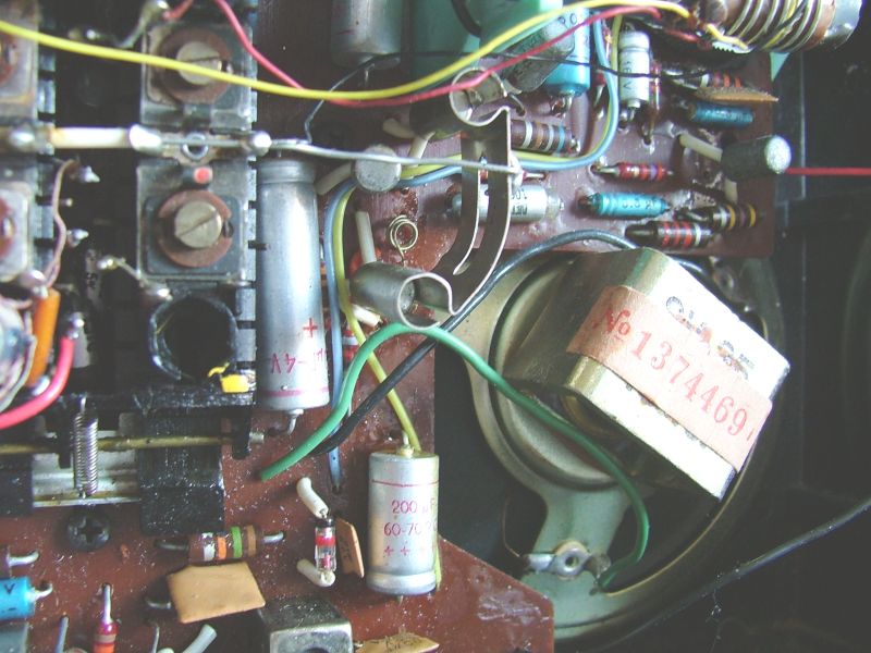
Generale di Elettricità - Milano - Italia, 1965 L'RT242 era un ricevitore portatile supereterodina con 2 bande di frequenza: Onde Medie e Onde Corte, il circuito utilizzava 7 transistor al germanio prodotti dalla ATES: AF168, AF172, AF172, AC137, AC138, AC142, AC141 e due diodi al germanio: un AA121 in rivelazione e un TA210, un transistor al germanio la cui giunzione Base/Emitter veniva utilizzata come diodo per il controllo della polarizzazione (bias). Per la ricezione delle Onde Corte bisognava estrarre l'antenna a stilo mentre per le Onde Medie l'antenna era avvolta su un lungo nucleo di ferrite. Il mobiletto era in plastica tipo similpelle con scala parlante rotonda e maniglia per il trasporto. L'alimentazione era fornita da 4 batterie da 1,5 V tipo C (LR14 o UM2). Particolare interessante: all'interno del coperchio posteriore era incollato lo schema elettrico del ricevitore. © IK3HIA, 2004 |
|||
 |
 |
 |
|
 |
 |
 |
|
 |
 |
 |
|
|
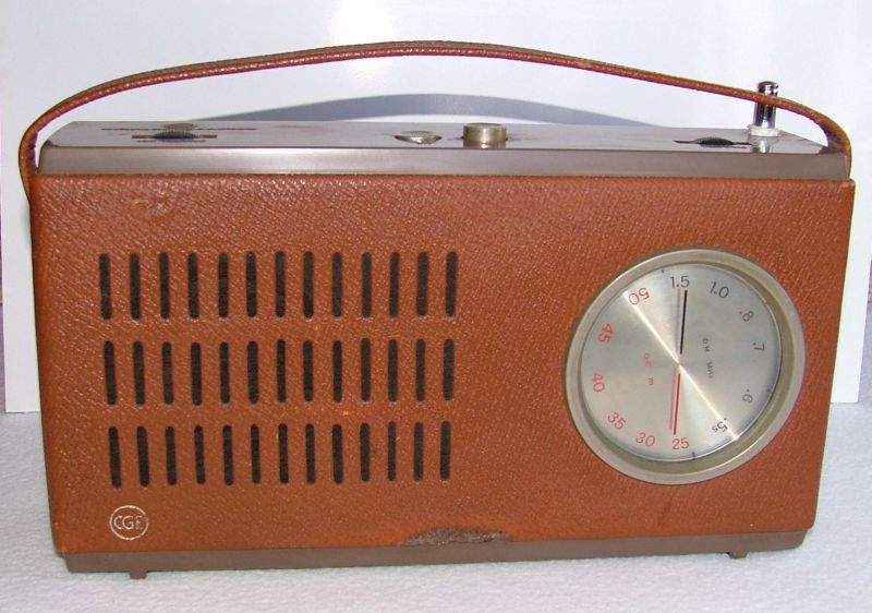
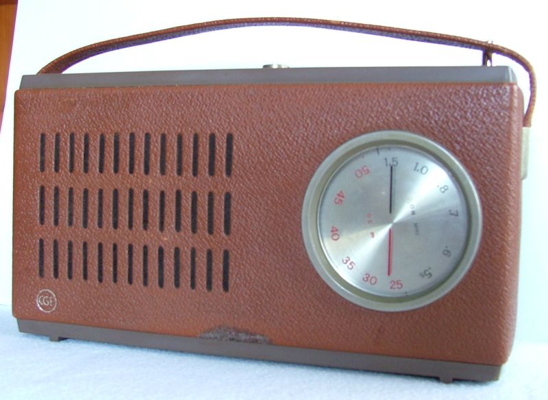
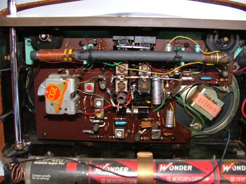
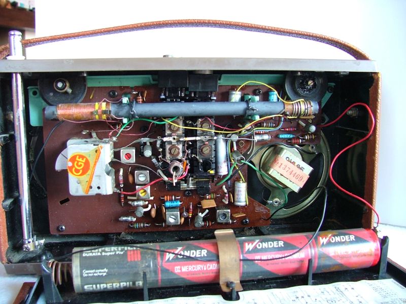
C.G.E. RT242 -
Compagnia Generale di Elettricita' - Milan - Italy 1965 The RT242 was a portable superheterodyne receiver with 2 frequency bands: Medium Waves and Short Waves, the circuit used 7 germanium transistors produced by ATES: AF168, AF172, AF172, AC137, AC138, AC142, AC141 and two germanium diodes: an AA121 in detection and a TA210, a germanium transistor whose Base/Emitter junction was used as a diode for polarization control (bias). For the reception of Short Waves it was necessary to extract the whip antenna while for Medium Waves the antenna was wound on a long ferrite core. The cabinet was made of imitation leather type plastic with a round dial and a handle for transport. The power supply was provided by 4 1.5 V type C batteries (LR14 or UM2). Interesting detail: the wiring diagram of the receiver was glued inside the back cover. © IK3HIA, 2004 |
|||
 |
 |
 |
|
 |
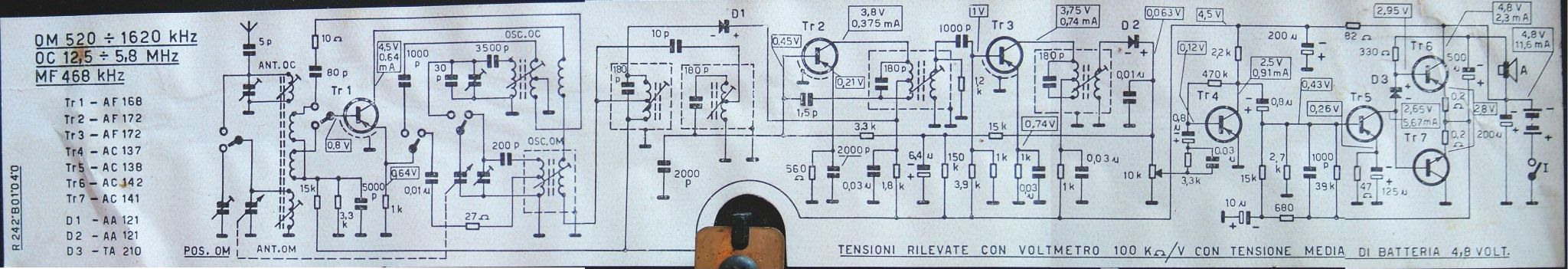
*Circuit diagram |
 |
|
|
Back to the top of the page >>
|
|||
|
|
Return to: IK3HIA home page |
|
Return to: Transistor Radio |
|
Go to: Transistor diagrams |