 |
GENERAL ELECTRIC P821A U.S.A. - 1961 |
|
|
|
GENERAL ELECTRIC P821A U.S.A. - 1961 |
|
|
|
 |
Description Electrical diagram |
|||
|
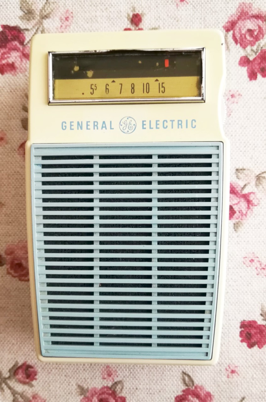
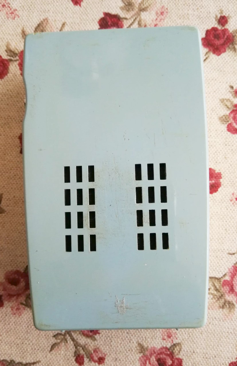
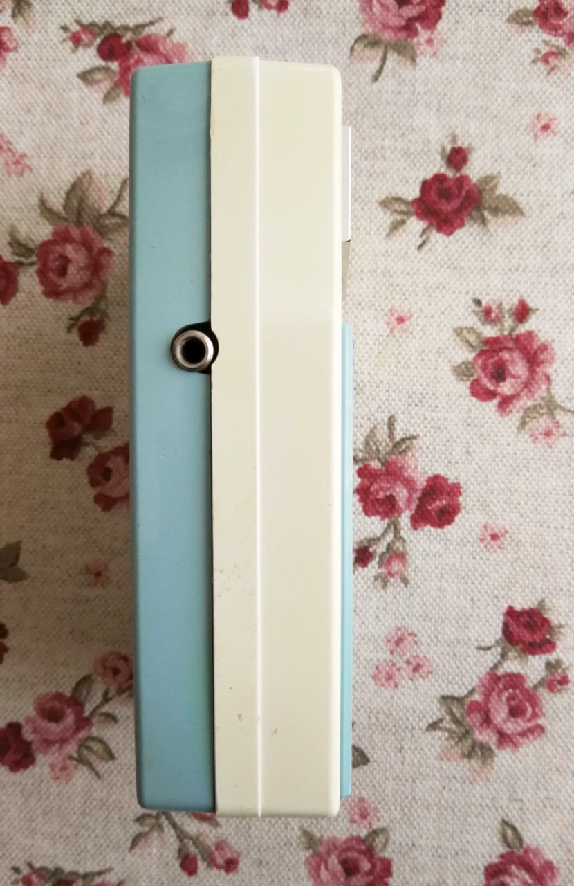
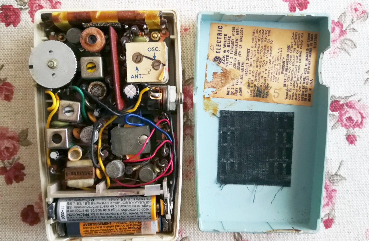
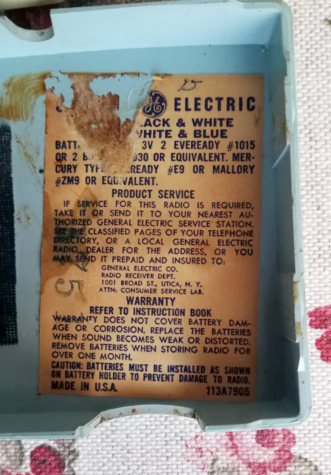
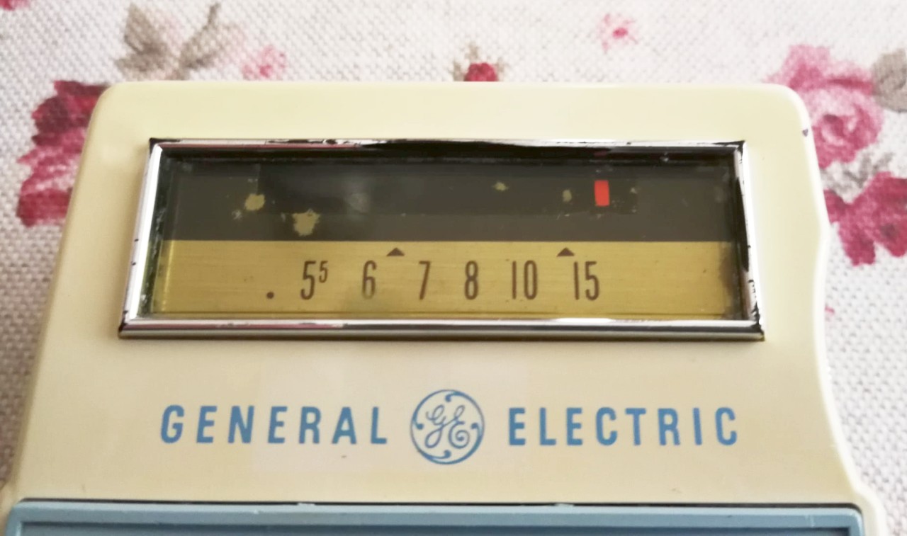
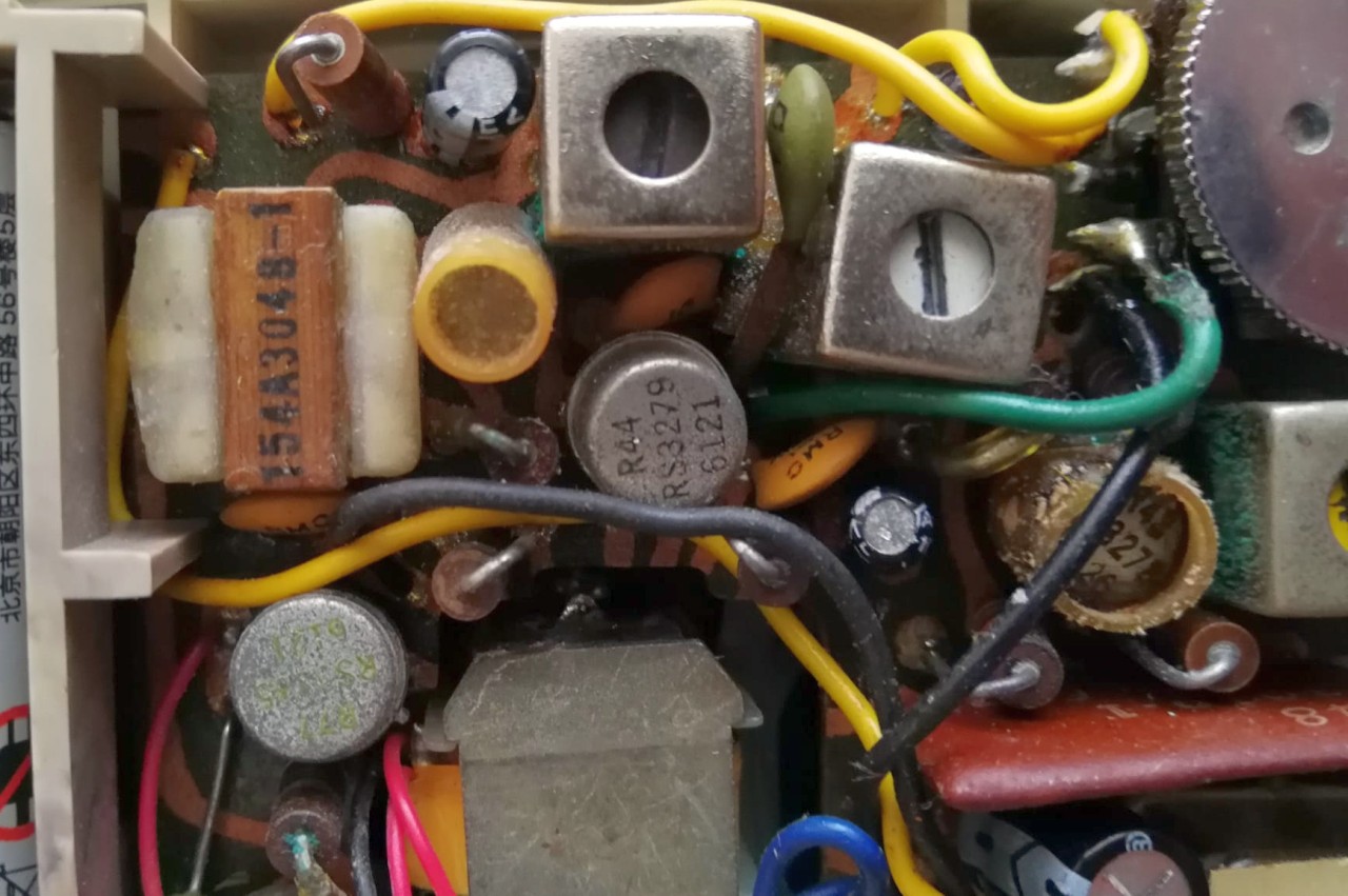
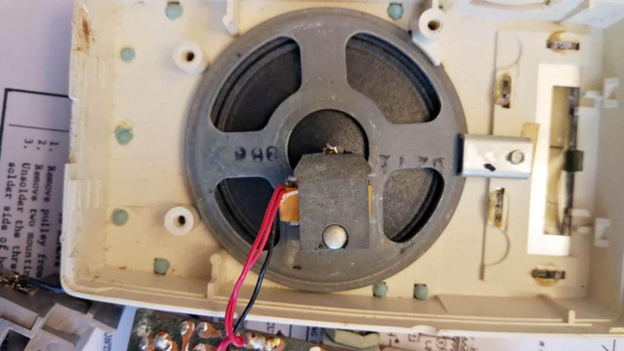
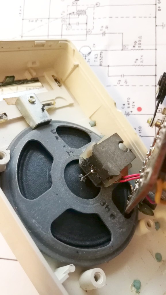
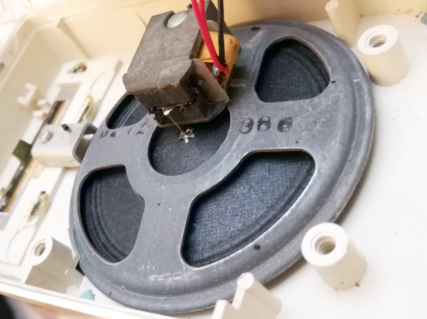
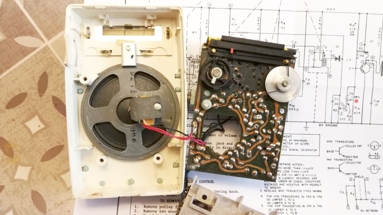
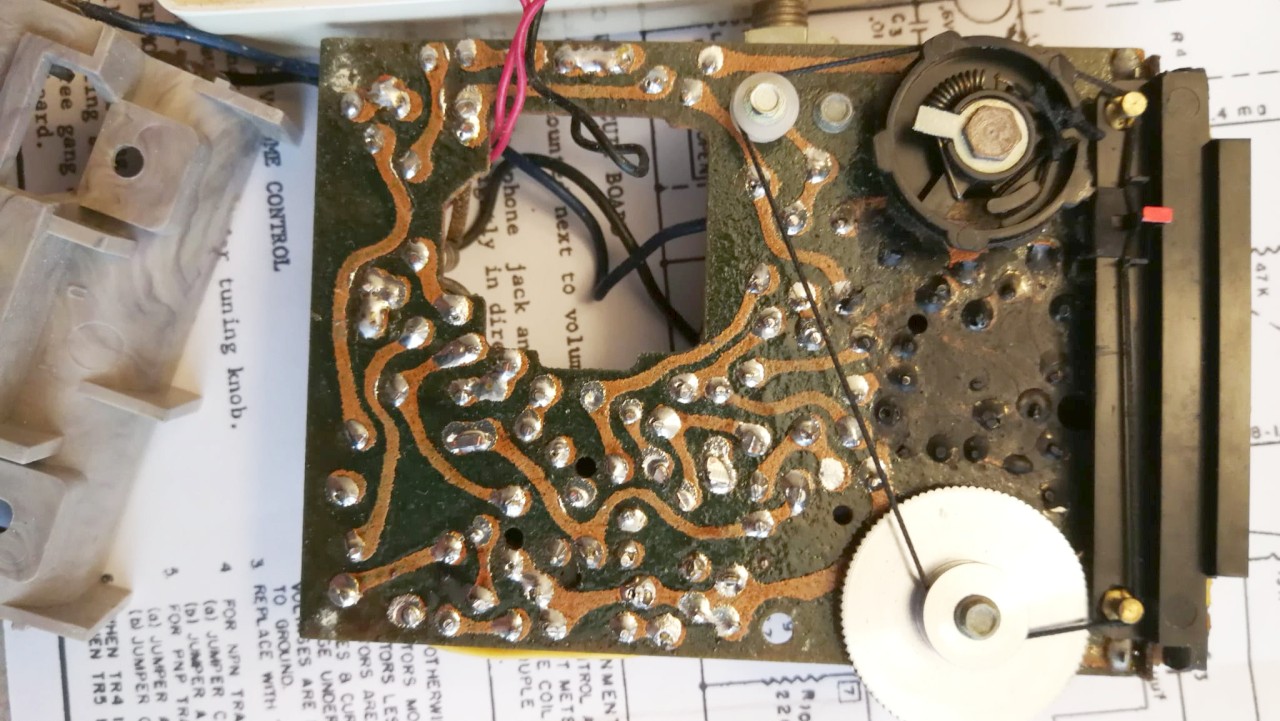
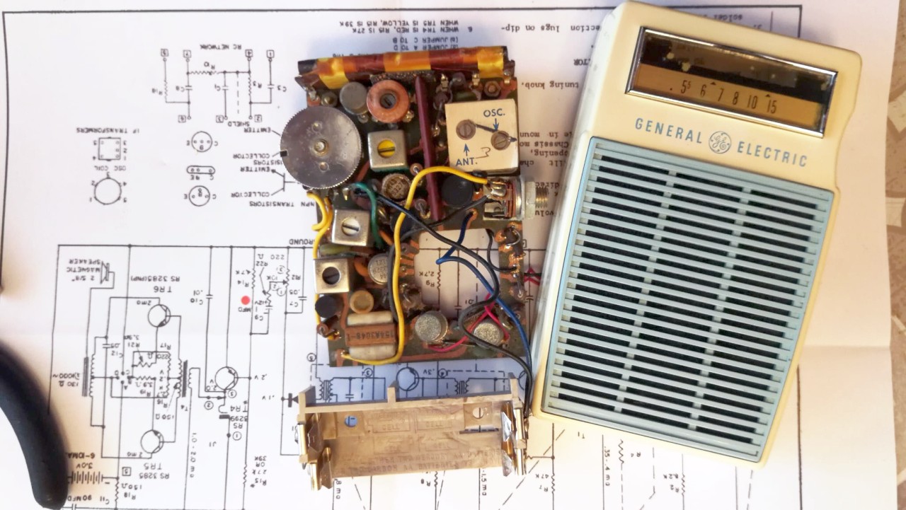
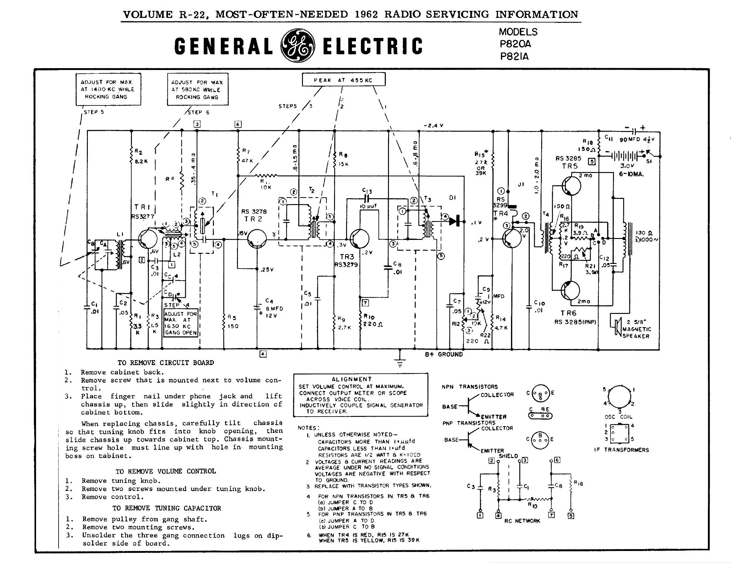
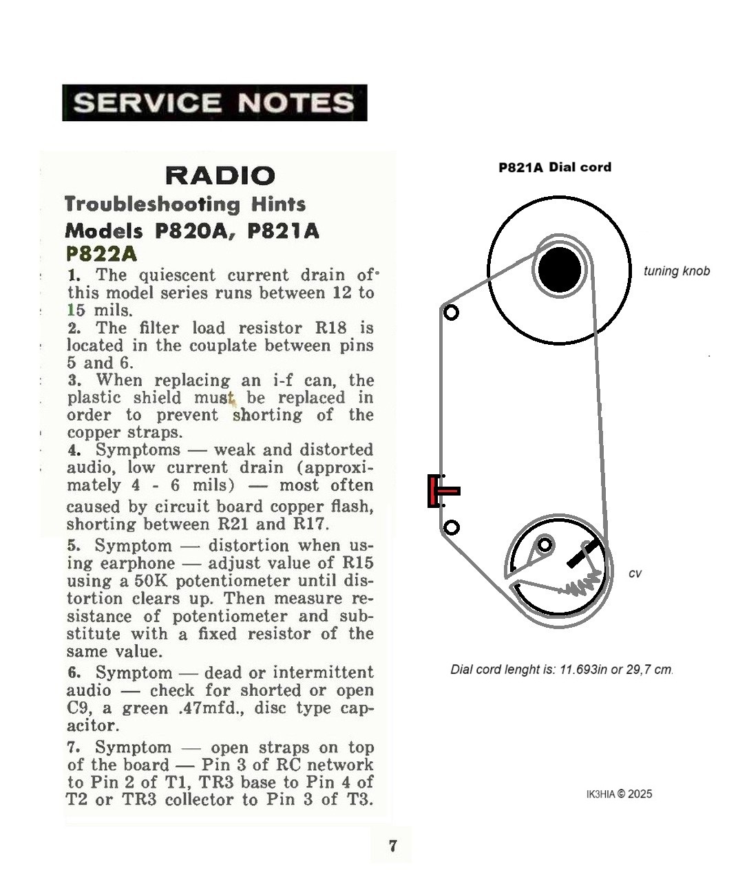
La P821A è una radio tascabile a transistor prodotta e commercializzata dalla General Electric negli Stati Uniti all'inizio degli anni '60. La radio veniva realizzata con il mobiletto in plastica bicolore con sigle diverse a seconda delle combinazioni: la P820A era bianca e nera; la P821A bianca e blu e la P822A era beige e bianca. La radio riceve le Onde Medie da 550 a 1550 kHz con Frequenza Intermedia a 455 kHz e utilizza sei transistor al germanio della General Electric: RS3277 Oscillatore-Convertitore, RS3278 1° Amplificatore di F.I., RS3279 2° Amplificatore di F.I., RS3299 Preamplificatore Audio e 2 x RS3285 in push-pull nell'Amplificatore di potenza Audio. Tramite dei ponticelli da spostare nel circuito audio della radio, come finali potevano essere utilizzate coppie di transistor PNP oppure NPN. La particolarità della P821A (e delle sue due sorelle) è l'altoparlante. Per risparmiare il trasformatore d'uscita, i tecnici della General Electric avevano pensato di riutilizzare una tecnologia in auge tra il 1920 e il 1930, quando si sviluppò una massiccia diffusione delle trasmissioni radiofoniche, ovvero quella dell'altoparlante a spillo. In questo tipo di trasduttore il cono di cartone è solidale con uno spillo che viene mosso da due avvolgimenti ad alta impedenza posti tra i poli di una calamita e che interagiscono con il segnale audio. Tale tipo di altoparlante ha una curva di risposta audio spostata verso le tonalità alte, ma ha anche un'alta efficienza ad alta impedenza, con un'avvolgimento con presa centrale, che nel caso della P821A è di 130 Ohm, le cui estremità sono collegate direttamente ai collettori dei transistor di potenza. Allora qual è il problema? Il problema è che se per qualche motivo si interrompe l'avvolgimento dell'altoparlante, per riparare questa radio non solo è necessario un altoparlante dello stesso diametro (2,62 pollici), ma bisogna assolutamente rimpiazzarlo con il ricambio originale General Electric che anche negli anni '60 era difficile da trovare. Fortunatamente l'esemplare di P821A che ho trovato su ebay era funzionante, appena alimentato con due pile da 1,5 V tipo AA poste in serie, dall'altoparlante sono usciti dei deboli segnali. Ho sostituito i tre condensatori elettrolitici presenti nel circuito e subito la P821A è ritornata a funzionare perfettamente. In questo foglio, oltre ad alcune note tecniche della G.E. ho riportato un disegno del percorso del cordino di sintonia. I controlli della sintonia e del volume sono posti sul lato destro superiore del mobiletto, sul lato sinistro invece c'è la presa per l'auricolare. Sulla scala parlante sono contrassegnate con dei triangolini le due frequenze (640 kHz e 1240kHz) del sistema di allarme nucleare CONELRAD in funzione negli Stati Uniti dal 1959. Maggiori informazioni in questo link. Le dimensioni della G.E. P821A sono 7,6 x 12,1 x 3,5 cm. © IK3HIA, 2025. |
|||||
|
|
|||||
 |
 |
 |
 |
||
 |
 |
 |
 |
||
|
The P821A is a pocket transistor radio produced and marketed by General Electric in the United States in the early 1960s. The radio was made with a two-tone plastic cabinet with different acronyms depending on the combinations: the P820A was black and white, the P821A was white and blue and the P822A was beige and white. The radio receives Medium Waves from 550 to 1550 kHz with Intermediate Frequency at 455 kHz, and uses six General Electric germanium transistors: RS3277 Oscillator-Converter, RS3278 1st F.I. Amplifier, RS3279 2nd F.I. Amplifier, RS3299 Audio Preamplifier and 2 x RS3285 in push-pull in the Audio Power Amplifier. Moving some jumpers on the PCB, pairs of PNP or NPN transistors could be used as power amplifiers. The peculiarity of the P821A (and its two sisters) is the loudspeaker. To save the output transformer, the technicians of General Electric had thought of reusing a technology in vogue between 1920 and 1930, when a massive diffusion of radio broadcasts developed, this tecnology was called "pin speaker". In this type of transducer the cardboard cone is integral with a pin that is moved by two high impedance windings placed between the poles of a magnet, and that interact with the audio signal. This type of speaker has an audio response curve shifted towards the high tones, but it also has a high efficiency at high impedance, with a center-tapped winding, which in the case of the P821A is 130 Ohm, whose ends are connected directly to the collectors of the power transistors. So what is the problem? The problem is that if for some reason the speaker winding breaks, to repair this radio you will not only need a speaker of the same diameter (2.62 inch), but it absolutely must be replaced with the original General Electric spare part which was difficult to find even in the 60s. Fortunately the P821A example that I found on ebay was working, as soon as it was powered by two 1.5 V AA batteries placed in series, the speaker gave off some weak signals. I replaced the three electrolytic capacitors in the circuit and the P821A immediately returned to working perfectly. In this sheet, in addition to some technical notes from G.E., I have included a drawing of the tuning cord path. The tuning and volume knobs are located on the upper right side of the cabinet, while on the left side there is the earphone jack. On the dial are marked with triangles the two frequencies (640 kHz and 1240 kHz) of the CONELRAD nuclear warning system in operation in the United States since 1959. More information in this link. The dimensions of the G.E. P821A are 3 x 4.75 x 1.375 inch. © IK3HIA, 2025. |
|||||
|
|
|||||
 |
 |
 |
 |
||
 |
 |
 |
 |
||
|
Return to
top of page
|
|||||
|
|
Return to: IK3HIA home page |
|
Return to: Transistor Radio |
|
Go to: Transistor diagrams |