 |
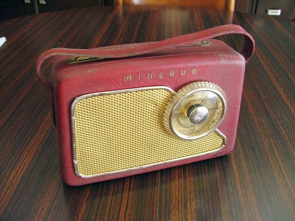
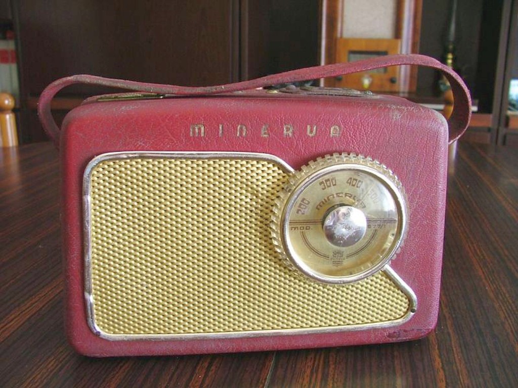
Minerva Picnic mod. 577/1 Italy -1957 |
|
|
Minerva Picnic mod. 577/1 Italy -1957 |
|
|
English |
||
|
|
|||
|
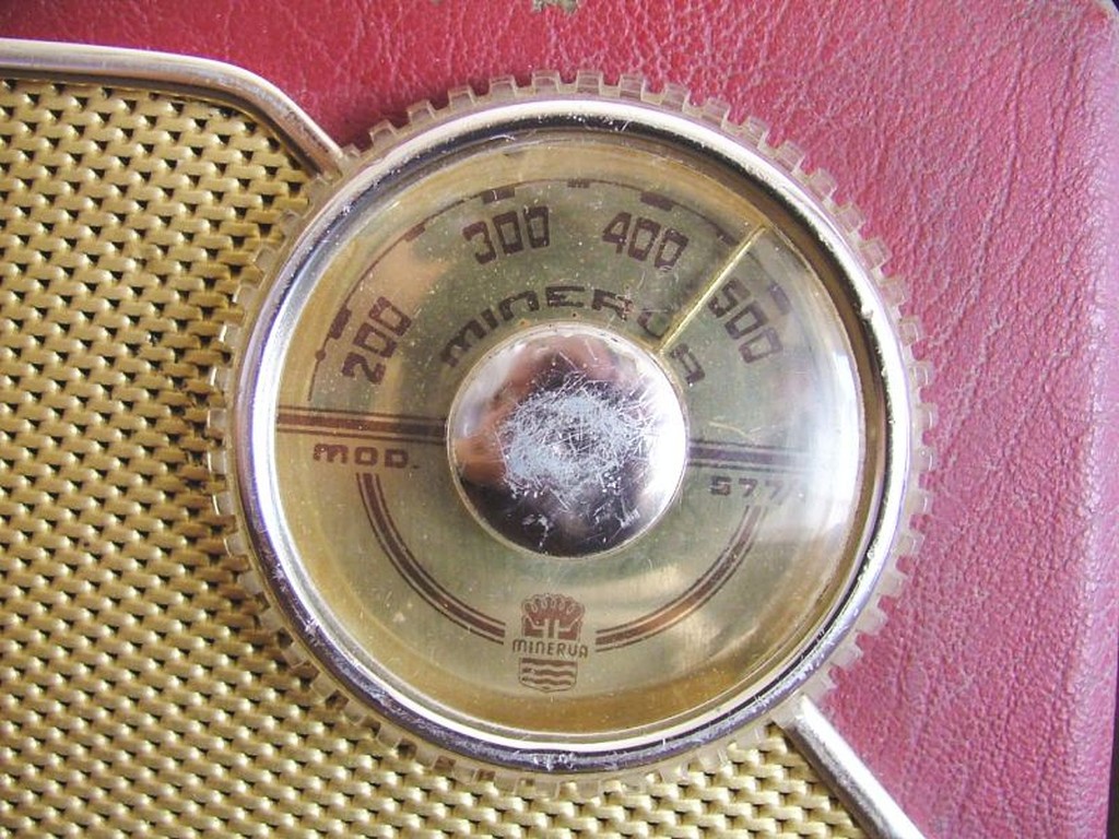
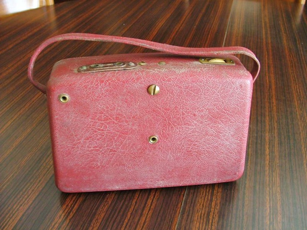
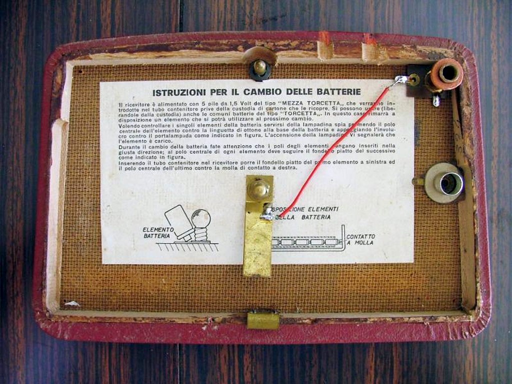
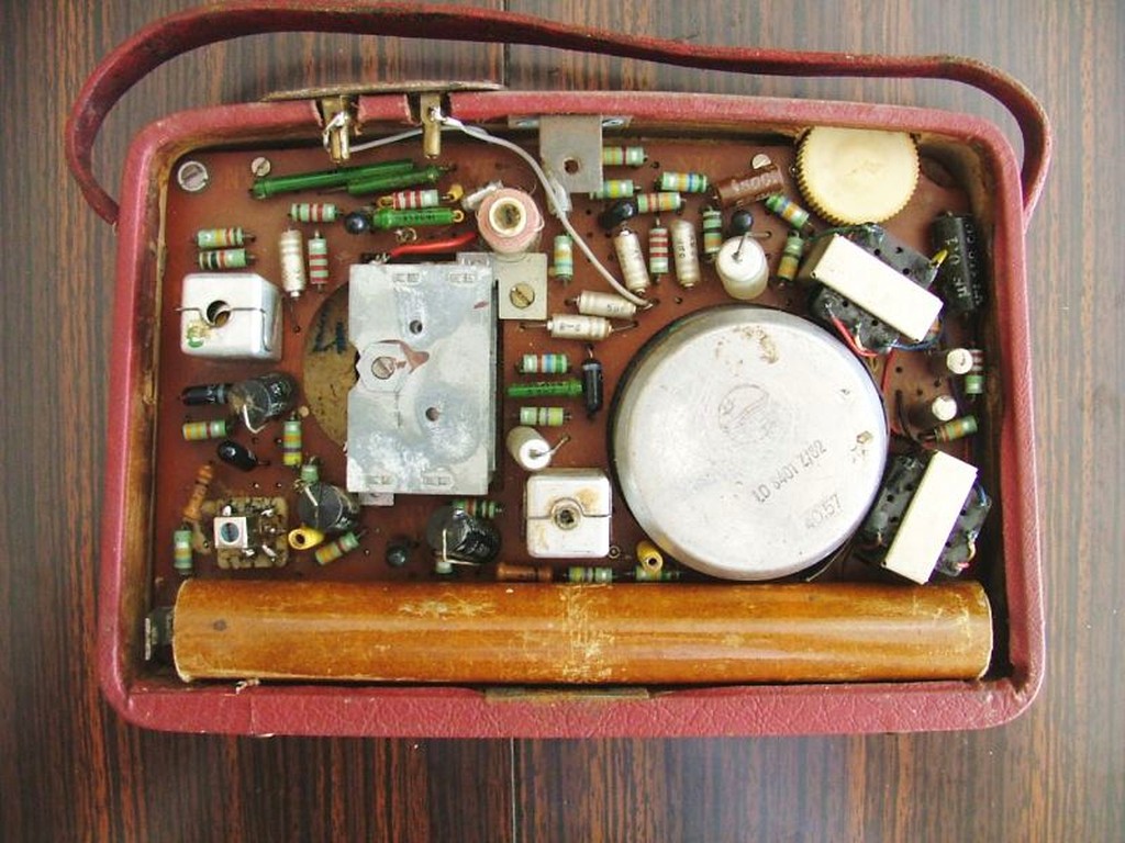
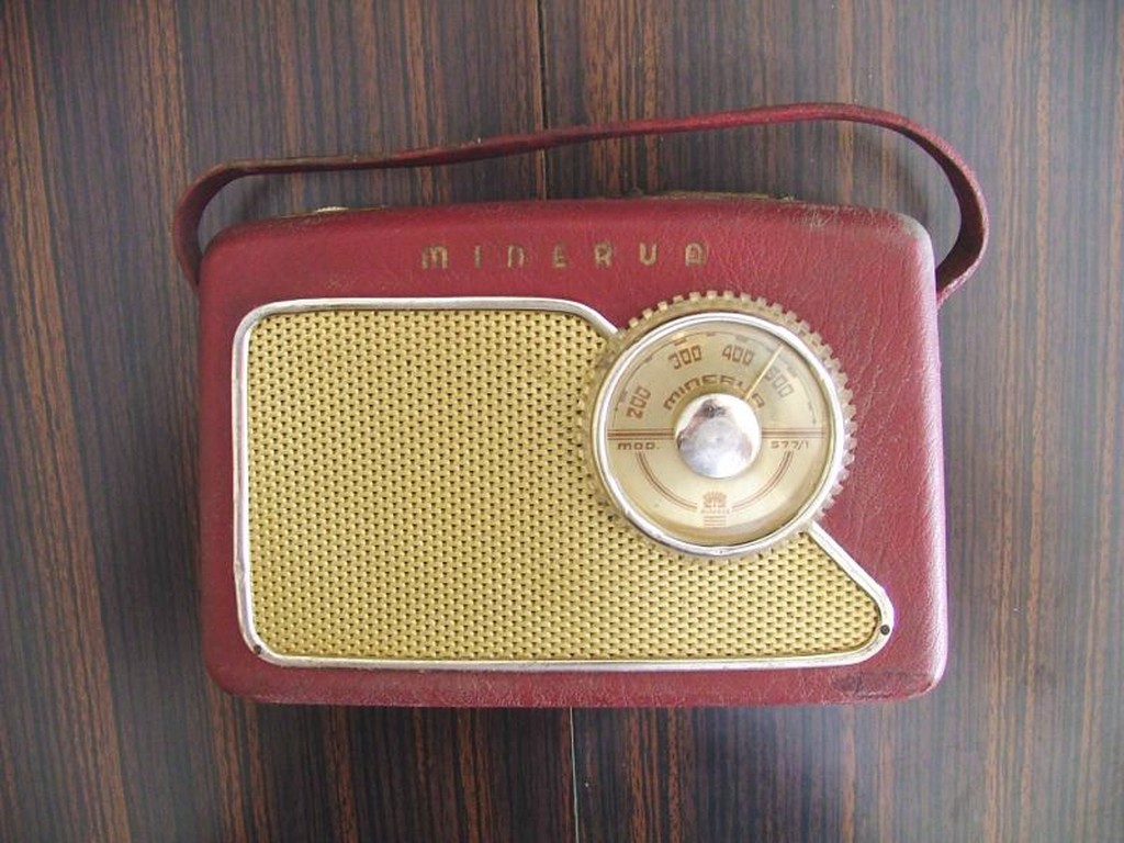
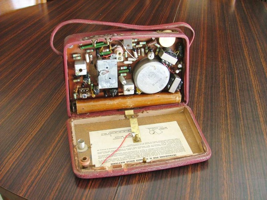
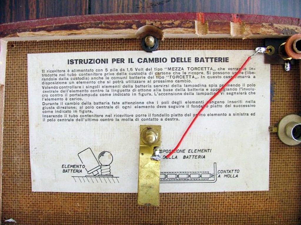
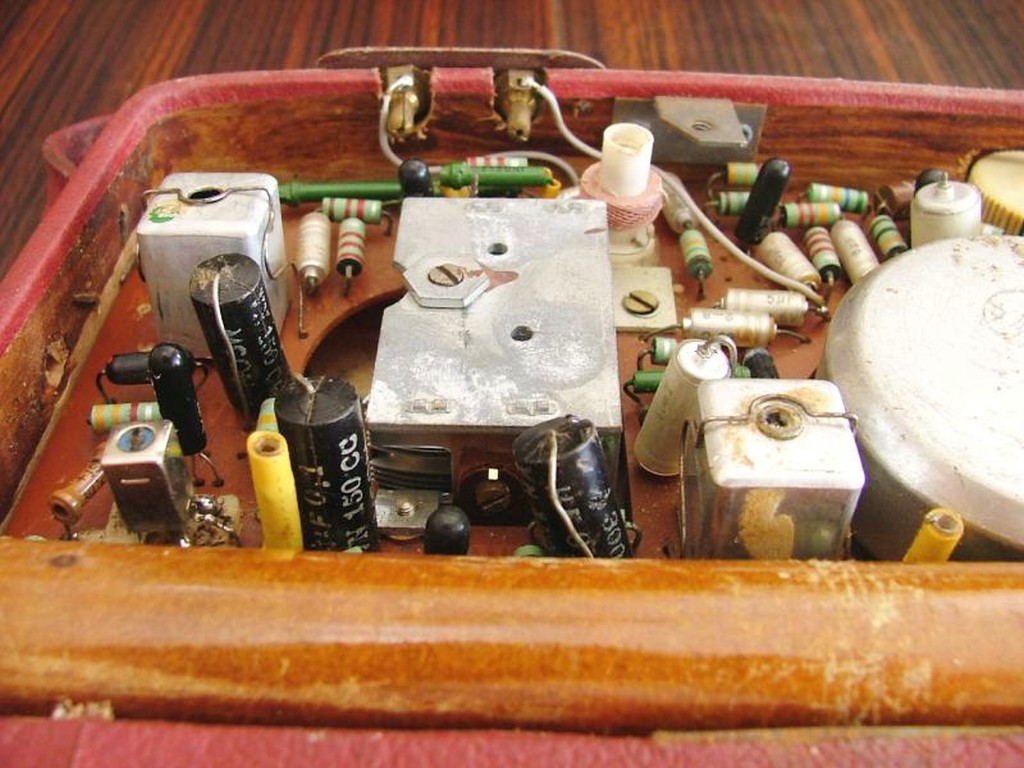
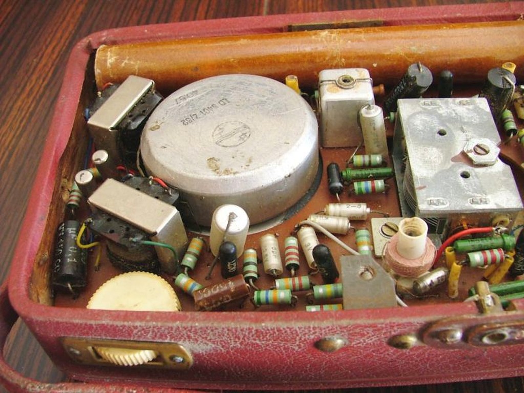
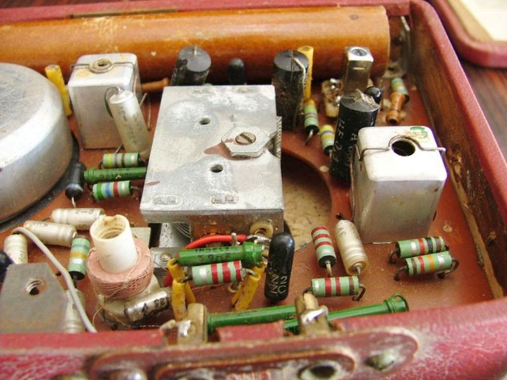
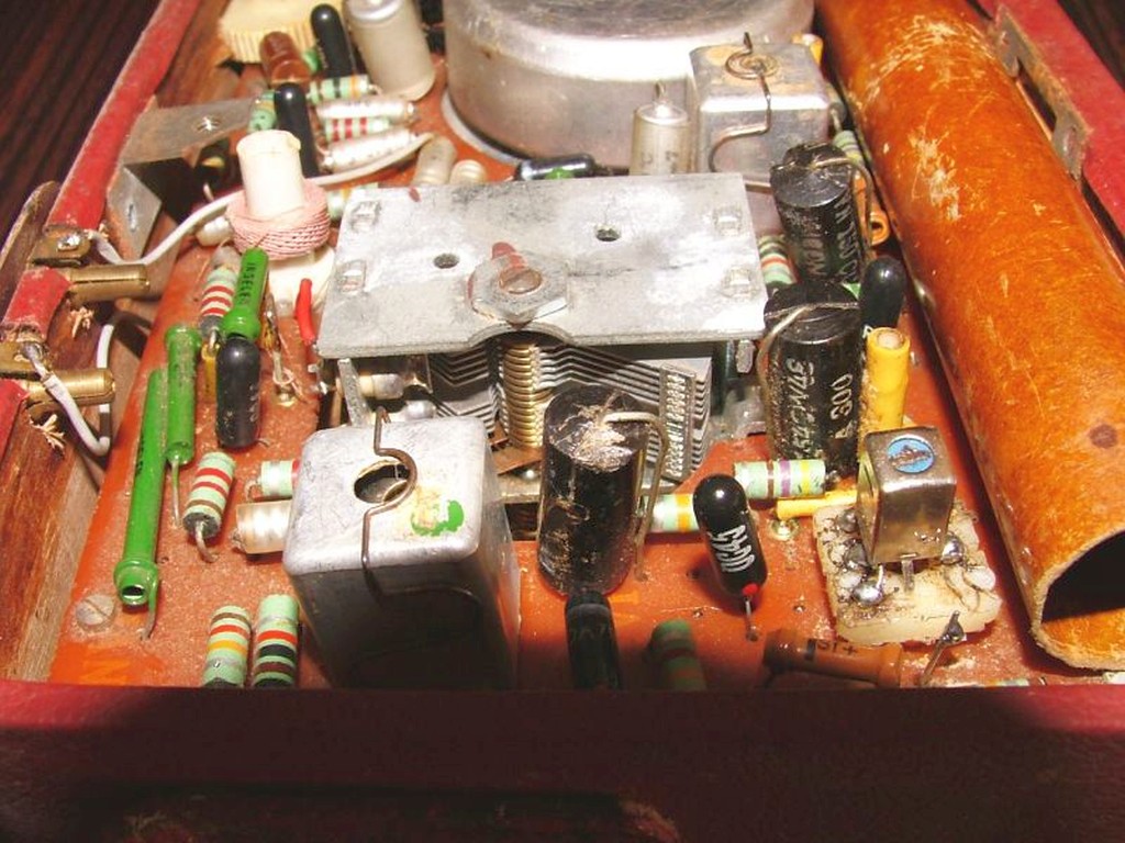
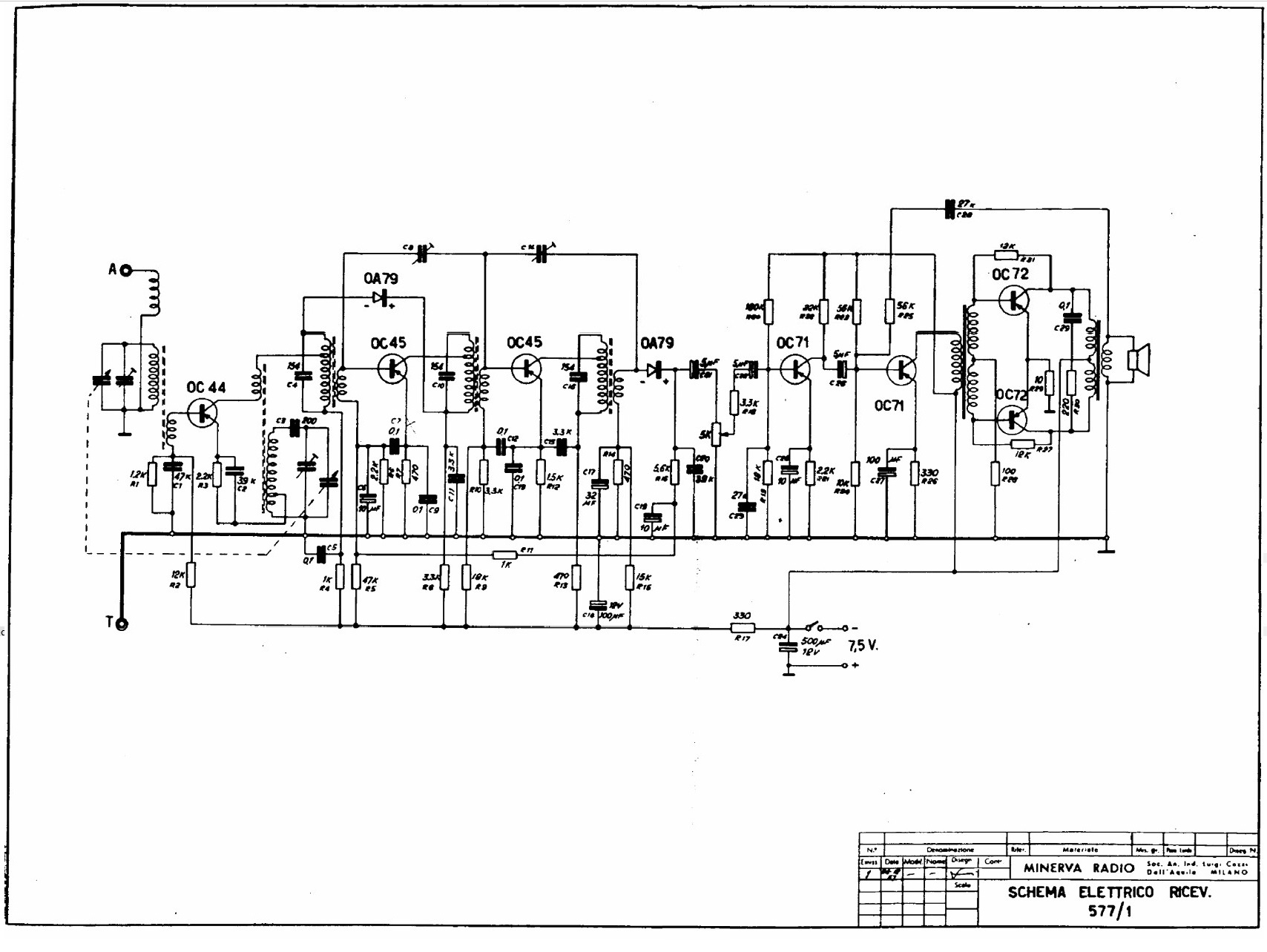
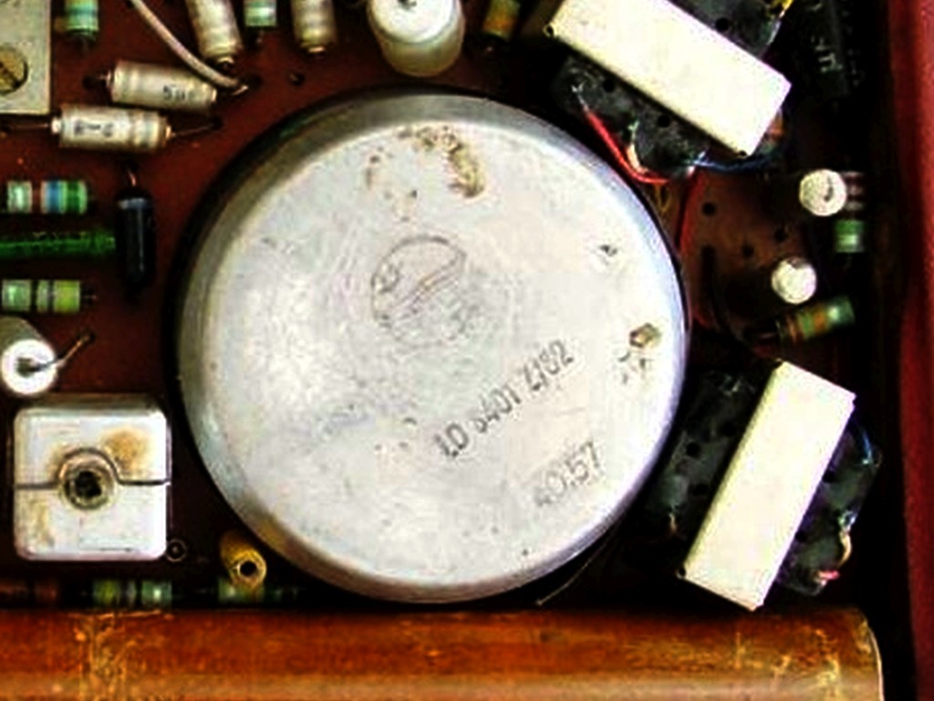
Ricevitore supereterodina portatile per la banda delle Onde Medie che utilizza 7 transistor della serie europea OC al germanio: OC44, OC45, OC45, OC71, OC71, OC72, OC72 e due diodi al germanio OA79. La Frequenza Intermedia risuonava a 470 kHz. L'antenna esterna o quella dell'auto poteva essere collegata a una boccola posta in alto a sinistra nel coperchio posteriore della radio, a un'altra boccola che si trovava al centro del coperchio fungeva da presa di massa. L'antenna esterna si accoppiava induttivamente al circuito d'ingresso della radio tramite una bobina sistemata nel coperchio posteriore. Uno dei capi della bobina era collegato alla presa d'antenna, l'altro invece si collegava tramite uno spezzone di filo alla presa di massa, la quale a sua volta tramite una linguetta flessibile di ottone era connessa alla massa della radio. Tale sistema di antenna doveva però essere poco pratico perchè nell'esemplare giunto in mio possesso qualcuno aveva aggiunto una presa di antenna e massa sulla parte superiore del mobile con l'evidente scopo di poterle collegare in qualche punto del circuito elettrico. Il mobiletto in legno era ricoperto di finta pelle ed era dotato di maniglia per il trasporto. L'altoparlante era un Philips da 10 cm = 3.9 inch, sul magnete del quale era impressa la sigla del modello e probabilmente la settimana di produzione del componente (40.57 = settimana dal 30 settembre al 6 ottobre 1957). La scala di sintonia rotonda con manopola demoltiplicata era sul davanti a destra, mentre il controllo del volume con interruttore di accensione era sulla parte sinistra superiore del mobile. L'alimentazione avveniva tramite 5 batterie da 1,5V tipo C (mezza torcia o LR14). Nel pannello posteriore c'erano le istruzioni e un portalampada con lampadina per effettuare il test delle batterie. Le dimensioni erano: 20x14,5x6,5 cm (L,A,P). Nel 1960 la Minerva lanciò sul mercato la Picnic 597/1, un ricevitore molto simile al modello precedente che non presentava innovazioni o miglioramenti. © IK3HIA, 2006. |
|||
 |
 |
 |
 |
 |
 |
 |
 |
|
Portable superheterodyne receiver for the Medium Wave band using 7 European OC series germanium transistors: OC44, OC45, OC45, OC71, OC71, OC72, OC72 and two OA79 germanium diodes. The Intermediate Frequency resonated at 470 kHz. An external or a car antenna could be connected to a socket located at the top left of the rear cover of the radio, another socket located in the center of the cover served to connect the ground. The external antenna was inductively coupled to the radio's input circuit via a coil located in the rear cover. One end of the coil was connected to the antenna socket, the other was connected via a piece of wire to the ground socket, which in turn was connected via a flexible brass tab to the ground of the radio. However, this antenna system must have been impractical because in the item that came into my possession someone had added an antenna and ground socket on the upper part of the cabinet with the evident purpose of being able to connect them at some point in the electrical circuit. The wooden cabinet was covered in fake leather and had a handle for carrying it. The speaker was a Philips large 3.9 inch, on the magnet of which was printed the model code and probably the week of production of the component (40.57 = week from September 30 to October 6, 1957). The round tuning dial with geared knob was on the front right, while the volume control with power switch was on the upper left side of the cabinet. The power supply was via 5 1.5V type C batteries (LR14). On the rear panel there were the instructions and a lamp holder with a bulb to test the batteries. The dimensions were: 20x14.5x6.5 cm (L,H,D). In 1960 Minerva launched the Picnic 597/1 on the market, a receiver very similar to the previous model with no innovations or improvements. © IK3HIA, 2006. |
|||
 |
 |
 |
 |
 |
 |
 |
|
|
Return to top of page
|
|||
|
|
Return to: IK3HIA home page |
|
Return to: Transistor Radio |
|
Go to: Transistor diagrams |