 |
Roberts R404 U.K. - 1965 |
|
 Description
 |
 |
Descrizione
Schema elettrico |
|||
|
|
|||||
 |
 |
 |
 |
||
|
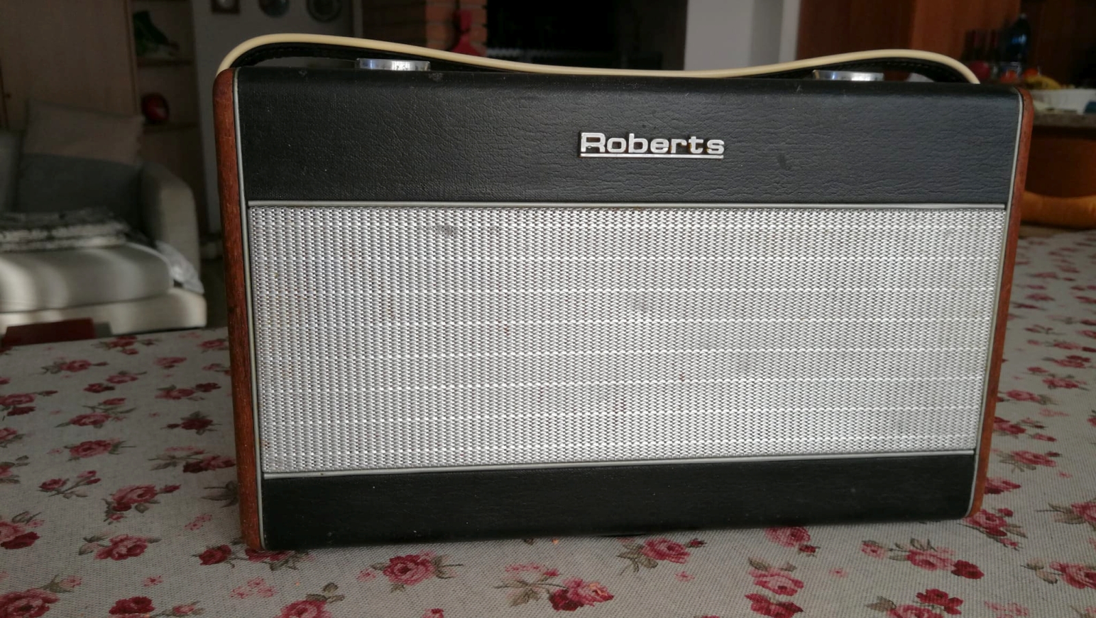
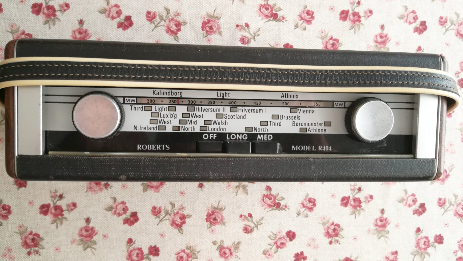
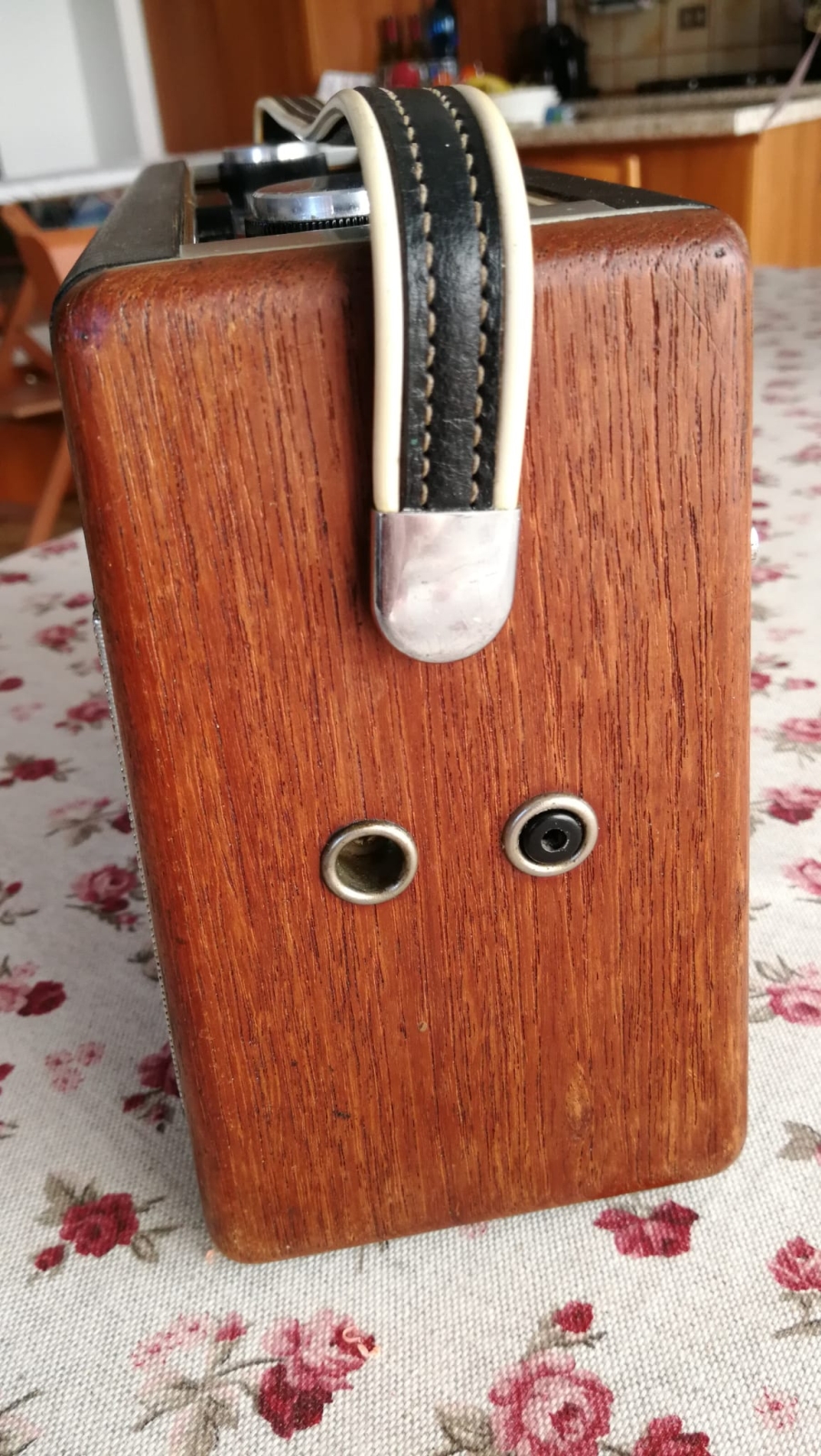
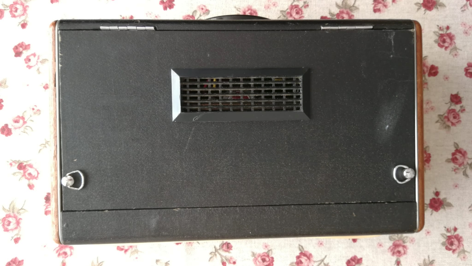
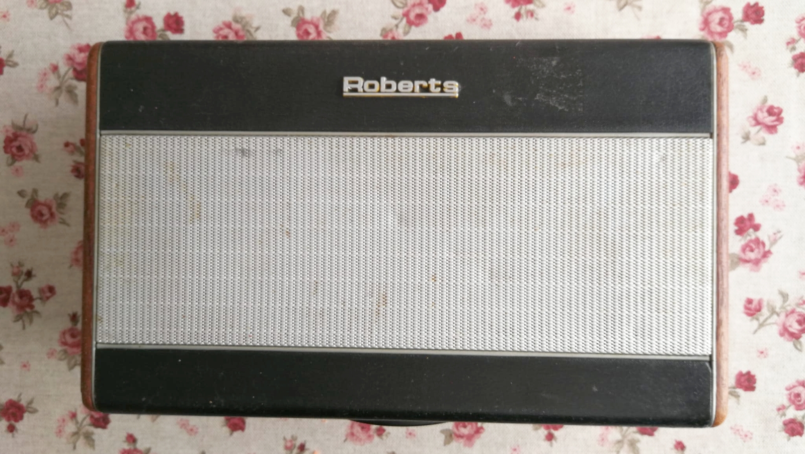
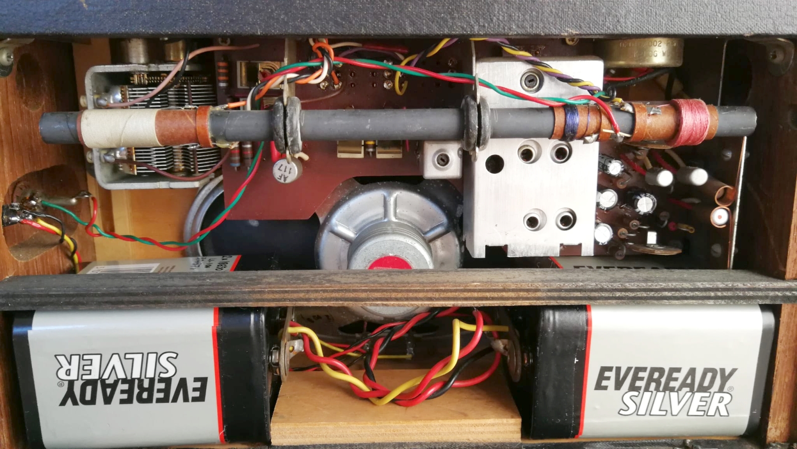
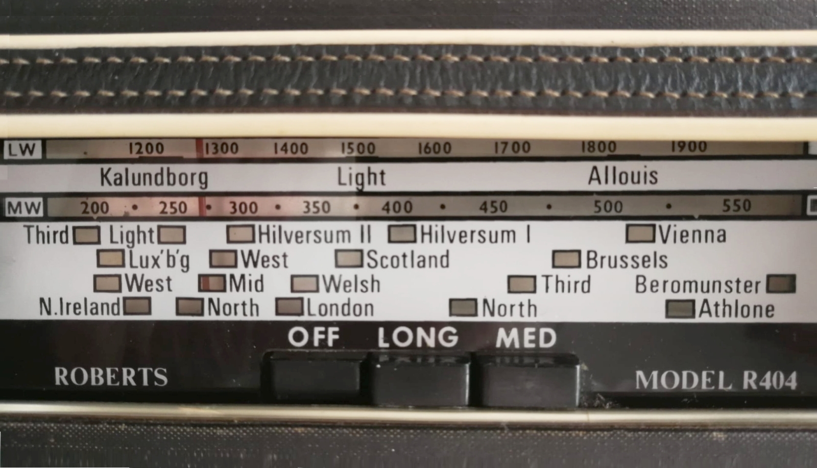
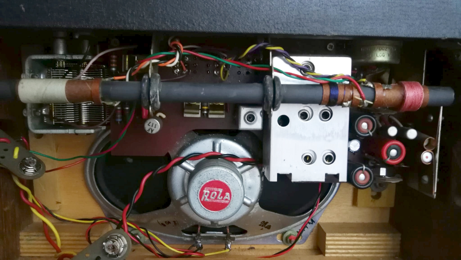
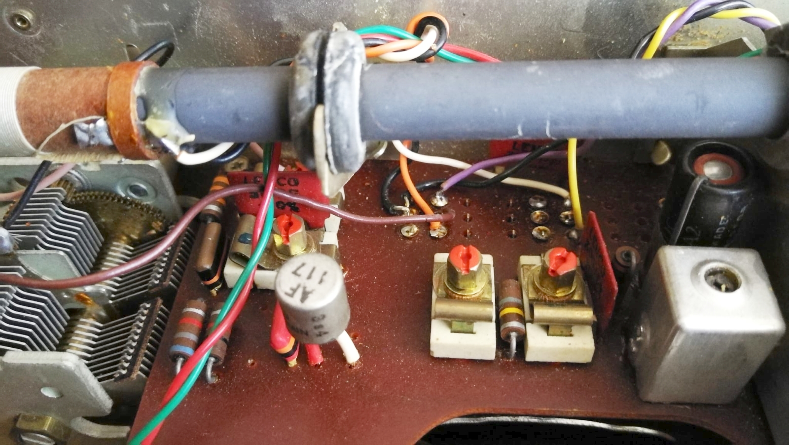
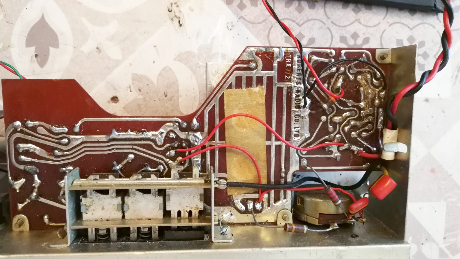
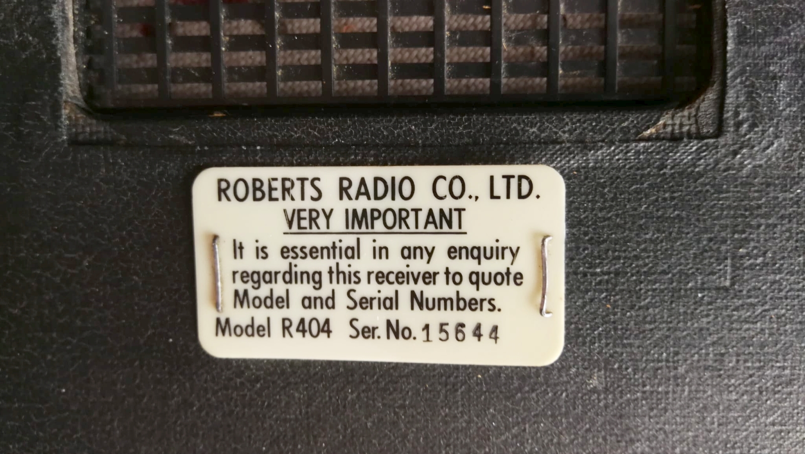
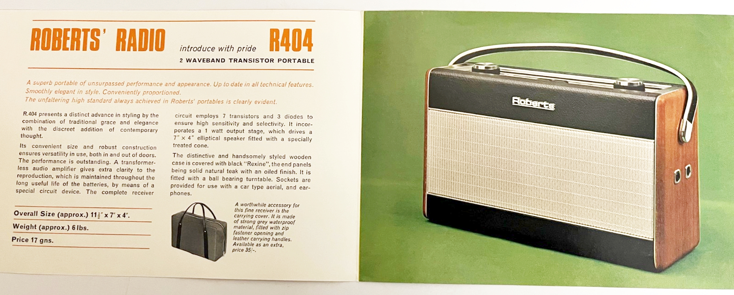
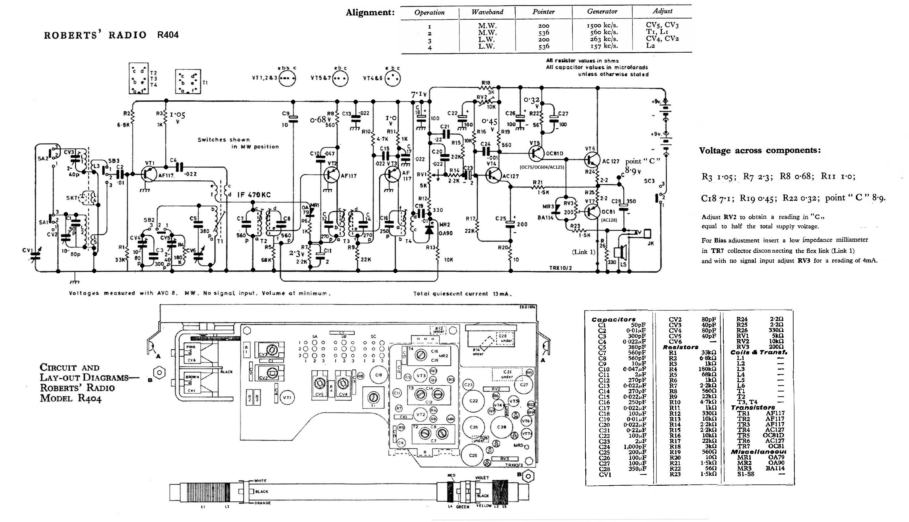
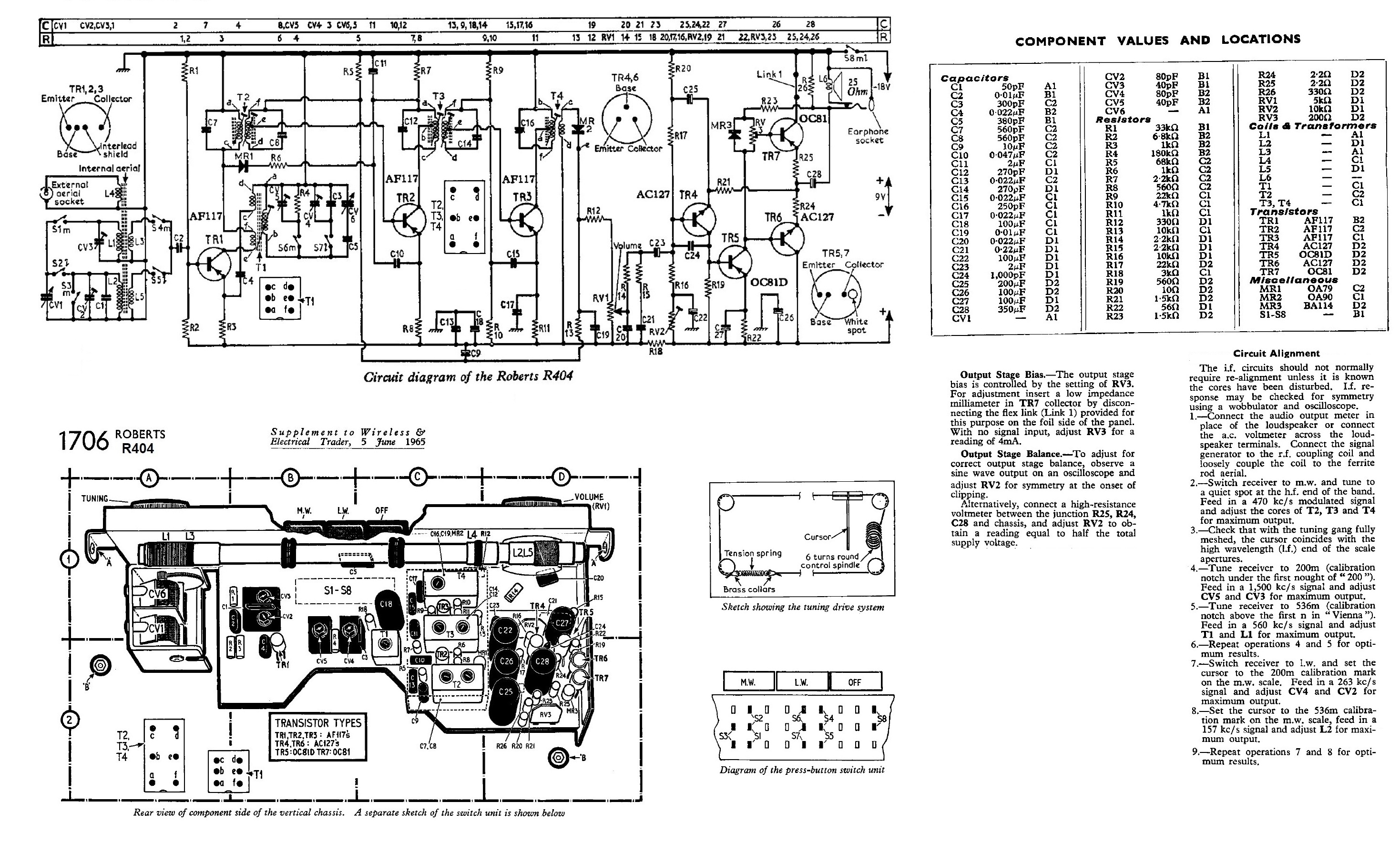
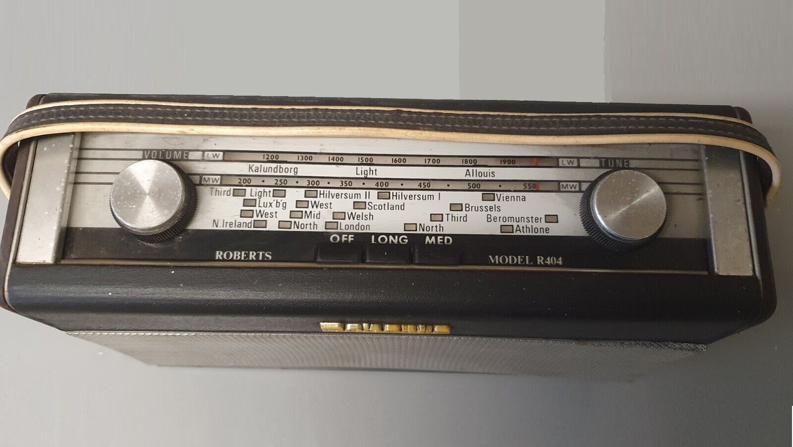
Le sigle adottate dalla Roberts per i propri modelli di radio non rispettavano una progressione temporale o logica. La R300 per esempio era uscita nel 1964 e la R303 nel 1967, posteriormente alla R404 che era stata commercializzata a partire dal 1965. La forma del mobile di legno delle radio inglesi era squadrata, lo stile del design era conservatore e le dimensioni rimanevano ragguardevoli, in netto contrasto con l'estrema miniaturizzazione che caratterizzava invece la produzione di radio giapponesi che in quegli anni avevano conquistato il mercato mondiale. Questo apparecchio utilizzava un circuito supereterodina con ricezione delle Onde Medie (da 183 a 570 metri) e delle Onde Lunghe (da 1120-2000 metri). Gli elementi attivi erano sette transistor al germanio: AF117, AF117, AF117, AC127, OC81C, AC127 e OC81, un diodo OA79 e un OA90 entrambi al germanio. I due transistor AF117 dello stadio a Frequenza Intermedia che risuonava a 470 kHz erano situati all'interno di un apposito modulo prodotto dalla Mullard e racchiuso in un contenitore di alluminio per la schermatura. I transistor di Alta Frequenza delle serie OC17x e AF11x prodotti nei primi anni sessanta, con il tempo erano soggetti al fenomeno dei "tin whiskers" ovvero alla crescita di sottilissimi baffi metallici nel materiale isolante posto all'interno del loro involucro. Crescendo, questi "baffi" dello spessore di qualche micron cortocircuitavano uno o più reofori del transistor con l'involucro metallico che era collegato a massa. Le soluzioni possibili erano due: applicare una scarica elettrica con una tensione di una trentina di Volt tra i reofori e l'involucro in modo da bruciare i baffi metallici, oppure sostituire il transistor con un equivalente al germanio della serie AF12x non afflitta dallo stesso problema. Maggiori informazioni sono visibili in questo link. L'amplificatore audio non utilizzava trasformatori ma uno schema a simmetria complementare NPN-PNP con la coppia di transistor AC127 e OC81 che forniva una potenza di uscita di 800 mW e in unione all'altoparlante ellittico Rola da 15.2 cm con impedenza di 25 Ohm avvitato al centro del pannello frontale del mobiletto di legno e forniva un discreto volume sonoro. L'antenna per OM e OL era avvolta su un lungo nucleo di ferrite ma sul pannello laterale destro del mobile era prevista una presa a cui poteva essere collegata un'antenna esterna per un eventuale utilizzo in auto. A fianco della presa d'antenna era situata anche una presa jack per cuffia. La scala parlante con i controlli di sintonia, del volume e la pulsantiera on-off e cambio gamma era situata sulla parte superiore del mobile, sotto la maniglia per il trasporto. Come tutti i precedenti ricevitori portatili Roberts prodotti a partire dagli anni '50, che erano dotati di antenna avvolta su nucleo di ferrite, anche la R403 aveva un disco di plastica girevole nella base, il quale permetteva la rotazione dell'apparecchio nella direzione della stazione emittente per ottenere il massimo segnale. L'alimentazione della R404 era fornita da due batterie da 9 V tipo PP9 poste in serie le quali permettevano una discreta autonomia. Le dimensioni della radio erano: 28 x 17 x 10 mm, e il peso era 1.9 kg senza le batterie. L'esemplare che sono riuscito a rintracciare aveva il numero di serie 15644 ed era funzionante, evidentemente qualcuno era intervenuto prima di me e aveva già risolto il problema dei "tin whiskers", così per completarne il restauro ho sostituito tutti i condensatori elettrolitici i quali, dopo sessant'anni di onorato servizio, presentavano resistenze interne e alterazione delle capacità. Inoltre ho pulito con l'apposito spray il potenziometro del volume e i contatti della pulsantiera cambio gamma-interruttore di accensione. IK3HIA © 2025. |
|||||
|
|
 |
 |
 |
||
 |
 |
 |
 |
||
|
Roberts R404 -
Roberts Radio Co. Ltd. - East Molesey, Surrey, U.K. - 1965 The designations adopted by Roberts for its radio models did not follow a chronological or logical progression. The R300, for example, was released in 1964 and the R303 in 1967, following the R404, which had been on the market since 1965. The wooden cabinets of the English radios were square, the design style was conservative, and the dimensions remained considerable, in stark contrast to the extreme miniaturization that characterized the Japanese radios that had conquered the world market in those years. This device used a superheterodyne circuit with reception of medium waves (183 to 570 meters) and long waves (1120 to 2000 meters). The active elements were seven germanium transistors: AF117, AF117, AF117, AC127, OC81C, AC127, and OC81, an OA79 diode, and an OA90, both germanium. The two AF117 transistors of the IF stage, resonating at 470 kHz, were located inside a special module produced by Mullard and enclosed in an aluminum case for shielding. High-frequency transistors of the OC17x and AF11x series, produced in the early 1960s, were subject to the "tin whiskers" phenomenon, the growth of very thin metal whiskers in the insulating material inside their casings. As these whiskers, a few microns thick grew, they short-circuited one or more of the transistor's leads with the metal casing, which was connected to ground. There were two possible solutions: applying an electric discharge with a voltage of about thirty volts between the leads and the casing to burn off the metal whiskers, or replacing the transistor with a germanium equivalent of the AF12x series, which was not affected by the same problem. More information can be found at this link. The audio amplifier used no transformers but a complementary symmetric NPN-PNP design, with the pair of transistors AC127 and OC81 providing an output power of 800 mW. In conjunction with the 6-inch Rola elliptical speaker with an impedance of 25 ohms, screwed to the center of the front panel of the wooden cabinet, it provided a decent volume. The AM and LW antenna was wound on a long ferrite core, but the right side panel of the cabinet featured a socket for connecting an external antenna for use in a car. A headphone jack was also located next to the antenna socket. The dial with the tuning and volume controls, and the on/off and band selection buttons were located on the top of the cabinet, under the carrying handle. Like all previous Roberts portable receivers produced since the 1950s, which featured a ferrite-core antenna, the R403 also had a rotating plastic disc in the base, which allowed the receiver to be rotated toward the broadcast station for maximum signal. The R404 was powered by two 9V PP9 batteries connected in series, which provided a reasonable battery life. The radio's dimensions were 11.5 x 7 x 4 inches, and it weighed 4 lb 3 oz without batteries. The item I was able to obtain had serial number 15644 and was in working order. Evidently, someone had already solved the "tin whisker" problem before me. So, to complete the restoration, I replaced all the electrolytic capacitors, which, after sixty years of faithful service, had internal resistance and altered capacitance. I also cleaned the volume potentiometer and the contacts on the range shift/power switch panel with a special spray. IK3HIA © 2025. |
|||||
 |
 |
 |
 |
||
|
Back to the top of the page
|
|||||
|
|
Return to: IK3HIA home page |
|
Return to: Roberts Radio page |
|
Return to: Transistor Radio |