 |
Roberts R606MB - U.K. 1975 |
|
 Description
 |
 |
Descrizione Schema elettrico |
|||
|
|
|||||
 |
 |
 |
 |
||
|
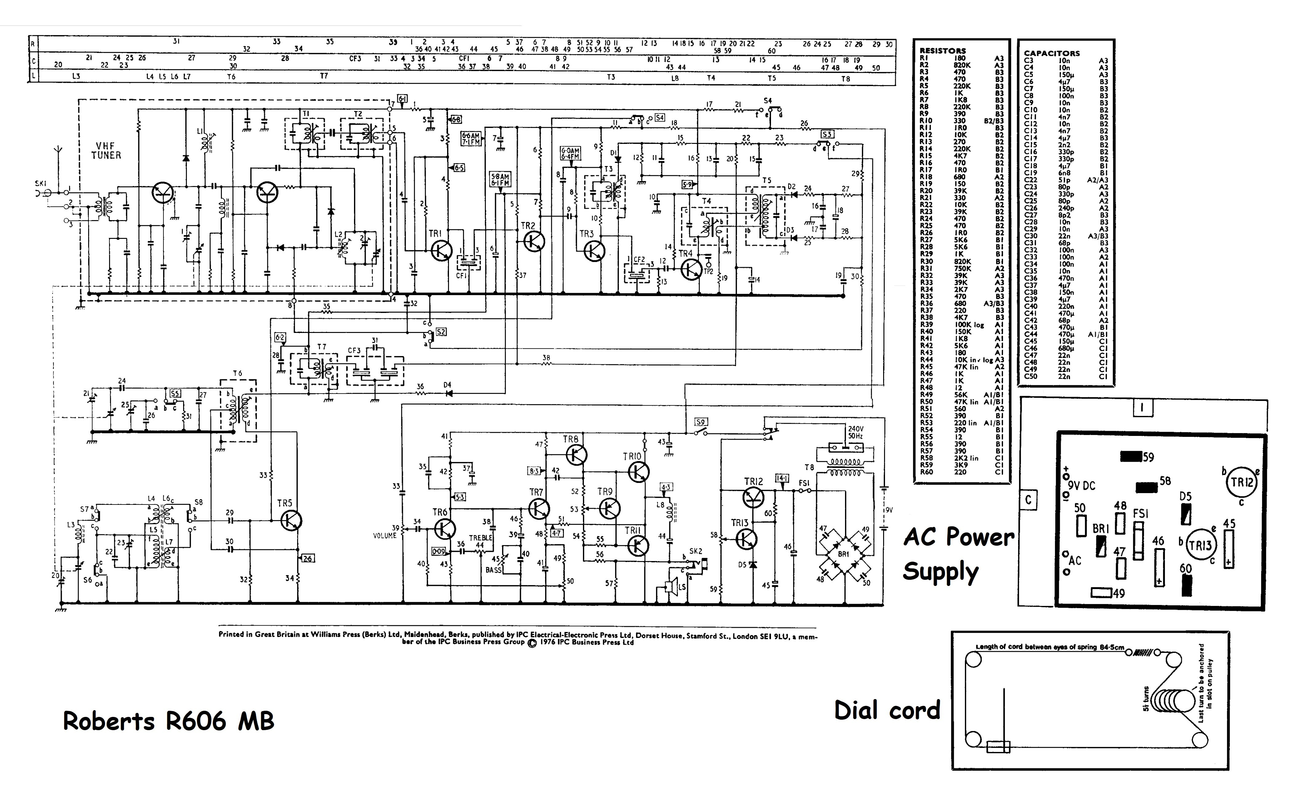
Il circuito elettrico impiegava tredici transistor al silicio: BF194, BF195, BF195, BF195, BF194, BC149, BC149, BC158, BC158, BC465, BC464, BD131, BC148. L'antenna per OM e OL era una bobina avvolta su nucleo di ferrite mentre per la FM la radio aveva uno stilo da 82,5 cm. Le frequenze intermedie erano rispettivamente a 470 kHz per la modulazione d'ampiezza e a 10700 kHz per la modulazione di frequenza. Lo stadio audio comprendeva il controllo del volume, dei toni acuti e dei toni bassi e il circuito di potenza a simmetria complementare forniva 1,2 Watt indistorti all'altoparlante ellittico da 10x17 cm con impedenza di 4 Ohm. Come nei ricevitori a transistor Roberts precedenti anche la R606MB era dotata del disco di plastica girevole alla base, che permetteva la rotazione dell'apparecchio per captare meglio il segnale in OM e OL. Nel pannello posteriore della radio erano previste una presa di antenna tipo autoradio e una presa jack da 3.5 mm per le cuffie. Sempre nella parte posteriore c'era la presa per il cavo della presa elettrica 240 Vac tipo C7. Oltre che dalla rete elettrica l'alimentazione poteva essere fornita anche da sei batterie da 1.5 V tipo C poste nella parte inferiore del mobile. Le batterie venivano automaticamente escluse quando si infilava il cavo con spina C nell'apposita presa. Purtroppo solo i 9 V erano escludibili con l'interruttore di accensione, perciò bisognava togliere la spina quando la radio non era in uso altrimenti il trasformatore rimaneva sempre sotto tensione. Il cabinet era di legno con pregiati pannelli laterali realizzati in teak, il resto era rivestito in finta pelle mentre la griglia anteriore aveva rifiniture cromate. Nella parte superiore destra la manopola di sintonia muoveva l'indice della scala parlante, a sinistra c'era il controllo del volume con l'interruttore di accensione mentre i controlli di tono e i pulsanti per il cambio gamma erano in alto. Le dimensioni erano: (LxAxP) 318 x 210 x 89 mm e il peso di 2 kg senza le batterie. L'esemplare pervenuto in mio possesso ha il numero di serie 650136 e solo per sicurezza ho sostituito i due condensatori elettrolitici C45 e C46 dell'alimentatore con componenti nuovi, poi ho smontato la radio per poter pulire con l'apposito spray i tre potenziometri (volume, toni alti e toni bassi). Il ricevitore è sensibile e molto stabile, con la parte FM che usufruisce di un filtro ceramico e di un circuito AFC (Automatic Frequency Control) disinseribile tramite apposito pulsante sulla scala parlante. IK3HIA © 2023. |
|||||
 |
 |
 |
 |
||
|
Return to top of page
|
|||||
|
The Roberts
R606MB was the evolution of the R606 model with the addition of a
stabilized power supply from 240 Vac to 9 Vdc. The device was a
superheterodyne that could receive Medium Waves (525 - 1630 kHz), Long
Waves (150 - 265 kHz) and FM with coverage of the VHF band from 87.5 to
104.5 MHz. The electrical circuit employed thirteen silicon transistors: BF194, BF195, BF195, BF195, BF194, BC149, BC149, BC158, BC158, BC465, BC464, BD131, BC148. The antenna was a coil wound on a ferrite core for OM and OL and an 32 31⁄64 in whip for FM. The intermediate frequencies were respectively 470 kHz for amplitude modulation and 10700 kHz for frequency modulation. The audio stage included volume, treble and bass controls and the complementary symmetry power circuit supplied 1.2 Watts undistorted to the 7 x 4 in elliptical speaker with 4 Ohm impedance. As in previous Roberts transistor receivers, the R606MB was also equipped with a rotating plastic disc at the base, which allowed the rotation of the device to better pick up the signal. A car stereo antenna socket and a 3.5 mm jack socket for headphones were provided in the rear panel of the radio. Also in the rear part was the type C7 socket for the 240 Vac net. In addition to the mains, power could also be supplied by six 1.5 V type C batteries placed in the lower part of the cabinet. The batteries were automatically excluded when the cable with C plug was inserted into the appropriate socket. Unfortunately the mains could not be excluded with the power on switch, so it had to be remembered to pull the plug out of the socket when the radio was not in use. The cabinet was made of wood with fine side panels made of teak, the rest was covered in imitation leather while the front grille had chrome trim. At the top right the tuning knob moved the pointer of the dial scale, at the left was the power on and the volume control while the tone controls and range change buttons were at the top. The dimensions were: (WxHxD) 12.5 x 8.3 x 3.5 inches and the weight 4 lb 6.5 oz (4.405 lb) without batteries. The copy that has come into my possession has the serial number 650136 and just to be safe I replaced the two electrolytic capacitors C45 and C46 in the power supply with new components, then I disassembled the radio to be able to clean the three potentiometers with the appropriate spray (volume, tone high and low tones). The receiver is sensitive and very stable, with the FM circuit using a ceramic filter and an AFC (Automatic Frequency Control) that can be disabled with a special button on the dial scale. IK3HIA © 2023. |
|||||
 |
 |
 |
 |
||
|
Return to top of page
|
|||||
|
|
Return to: IK3HIA home page |
|
Return to: Roberts Radio page |
|
Return to: Transistor Radio |