 |
Schaub-Lorenz Touring Automatik T40 West Germany - 1963 |
|
|
|
Schaub-Lorenz Touring Automatik T40 West Germany - 1963 |
|
| |
 |
Italiano
Restauro |
|||||
|
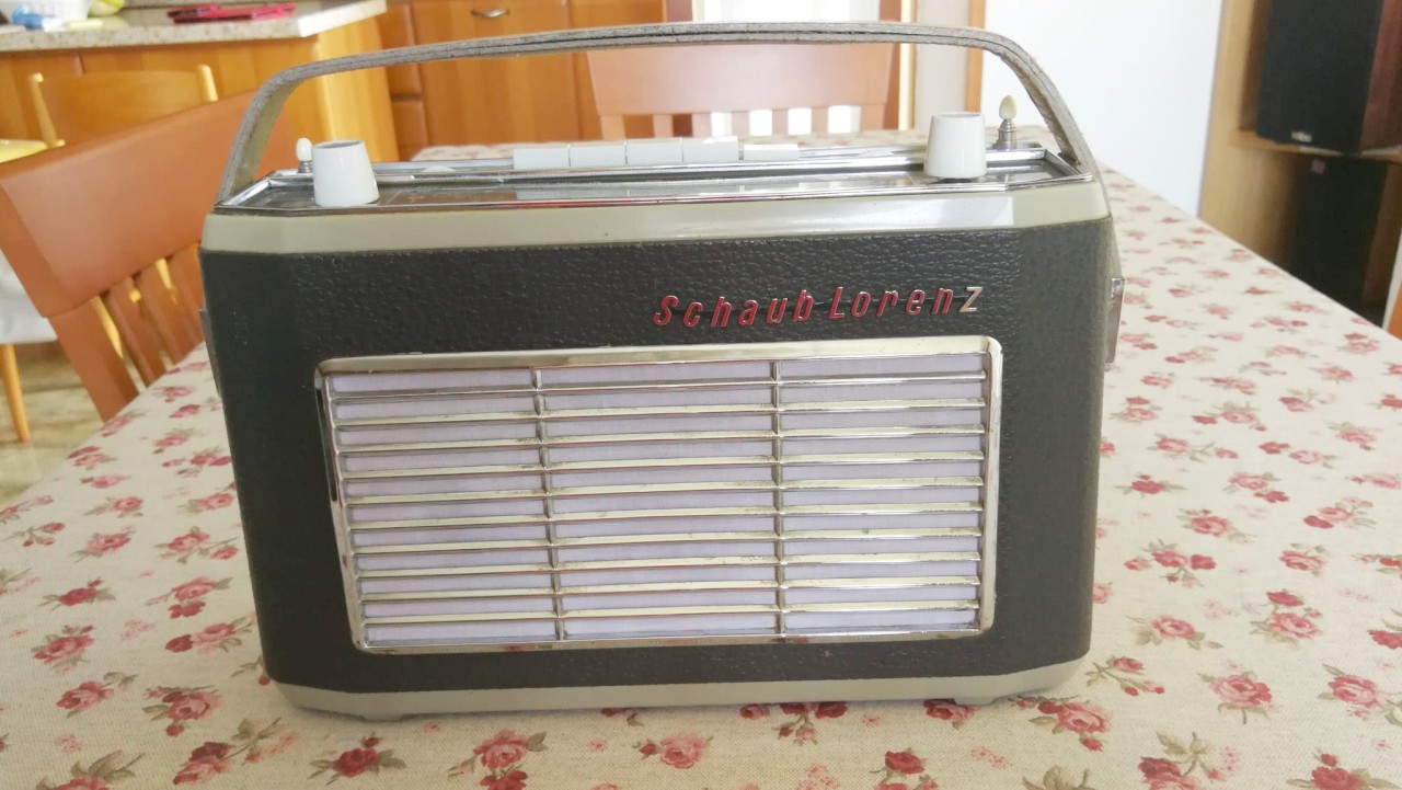
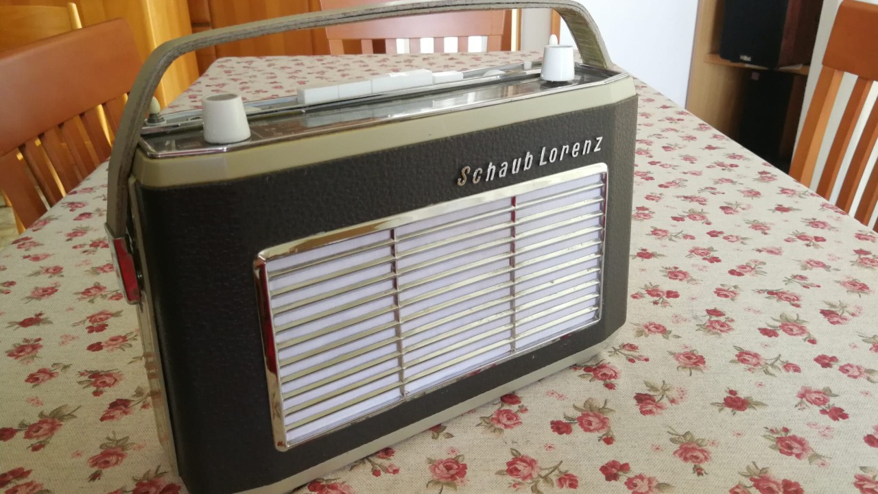
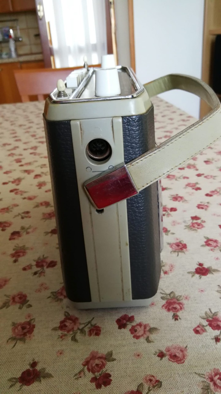
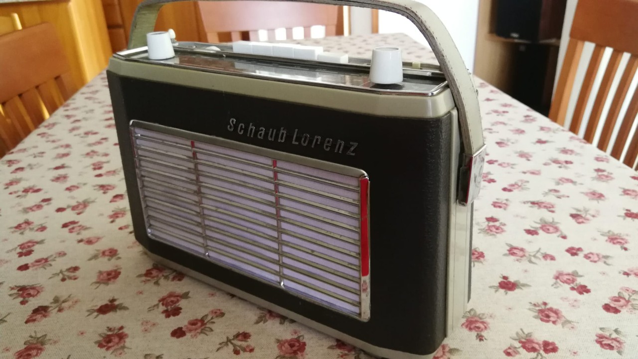
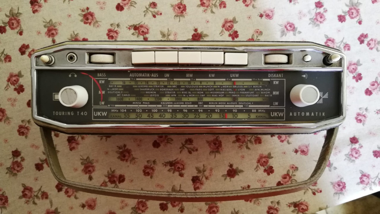
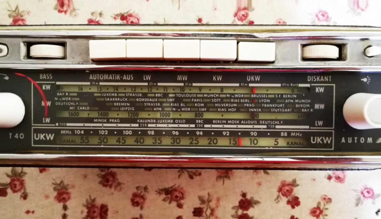
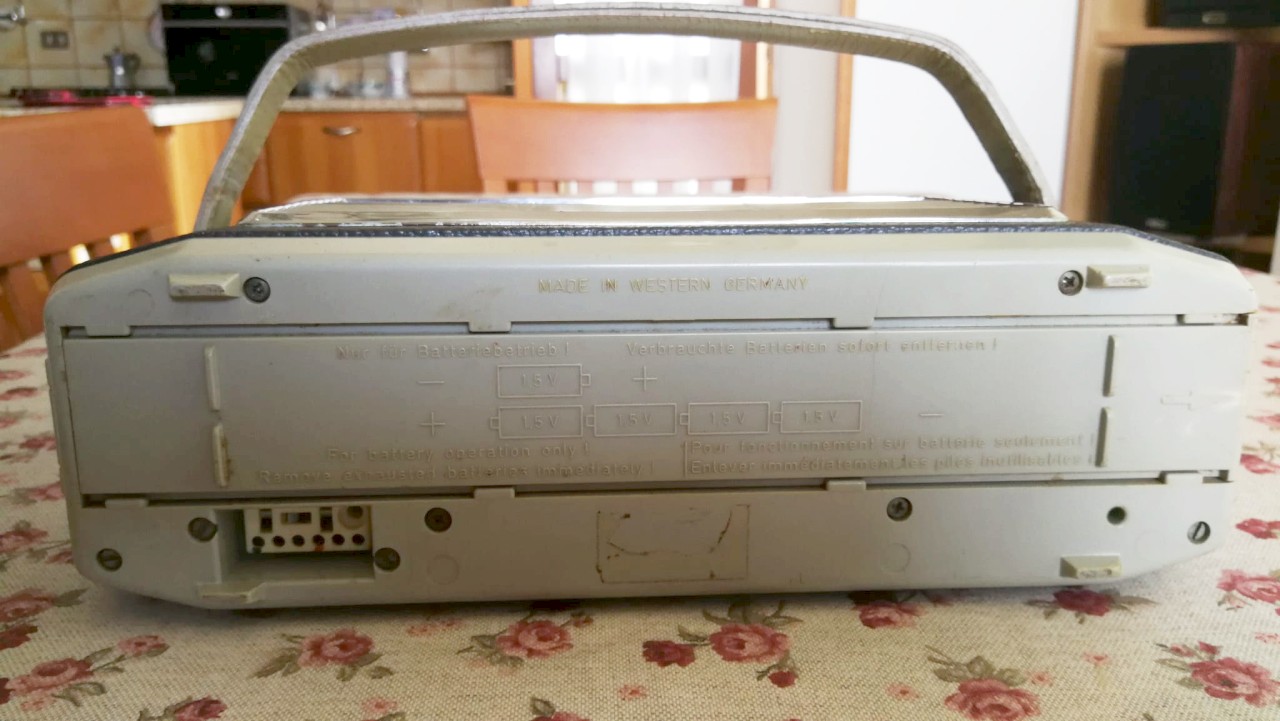
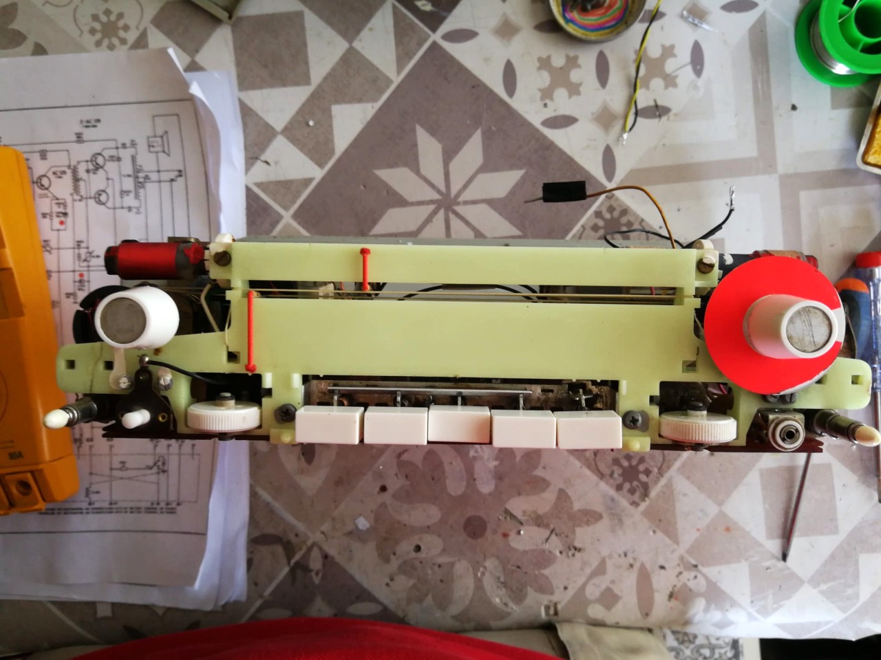
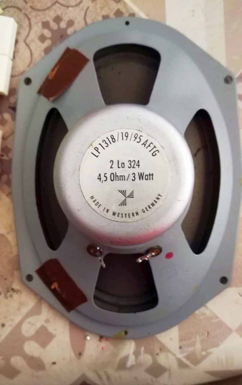
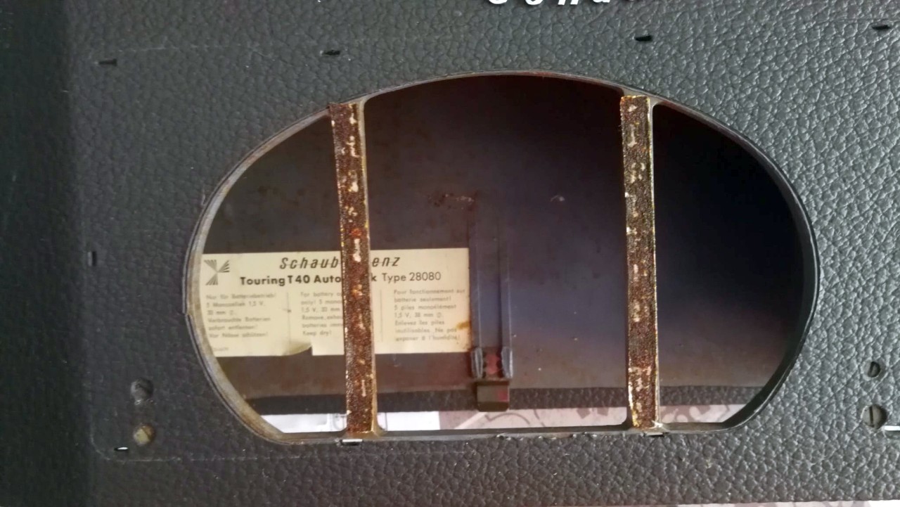
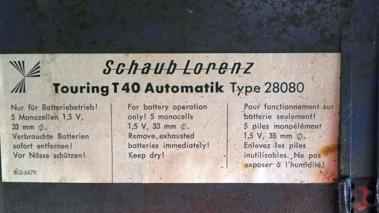
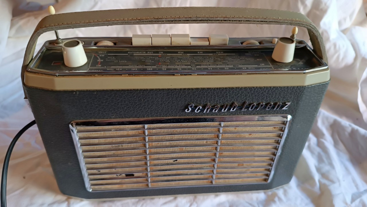
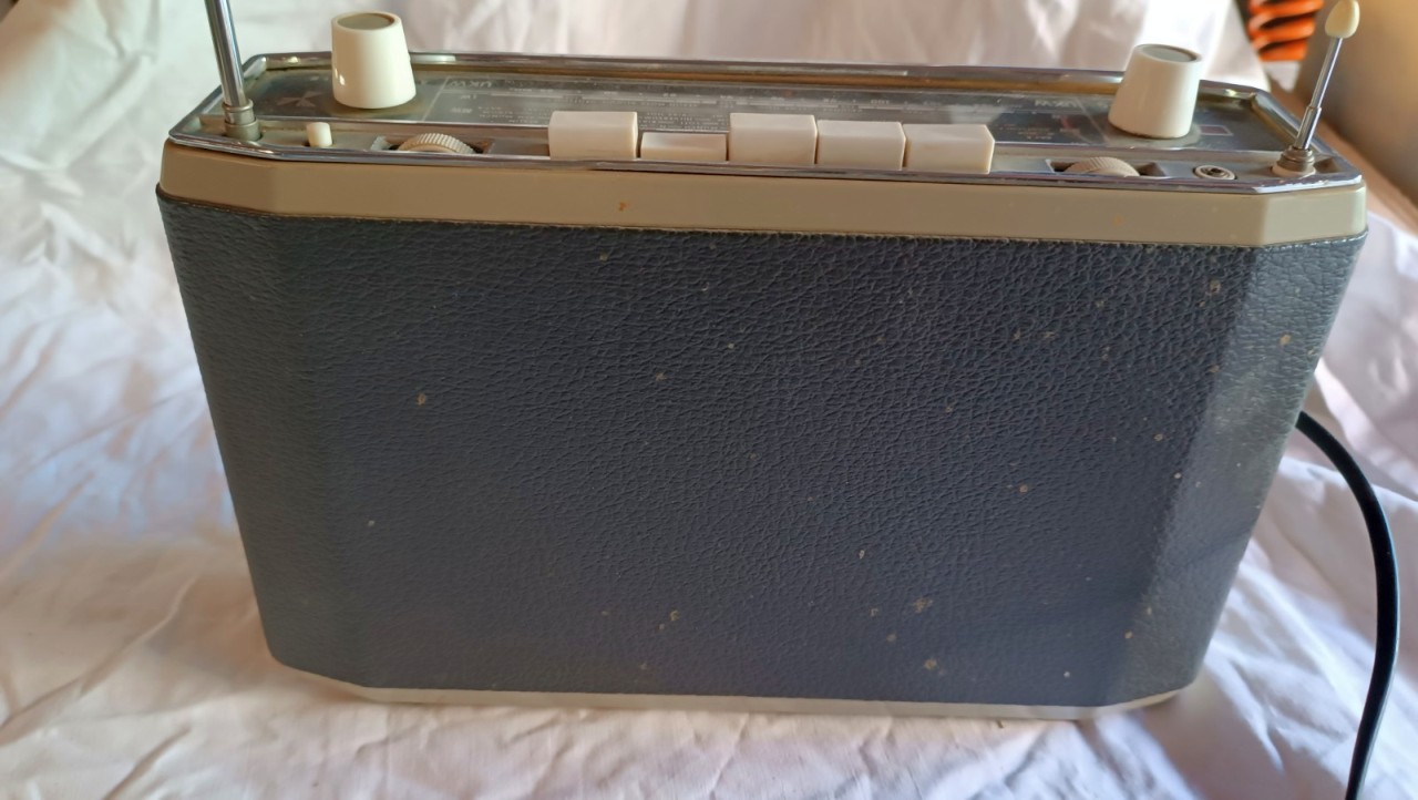
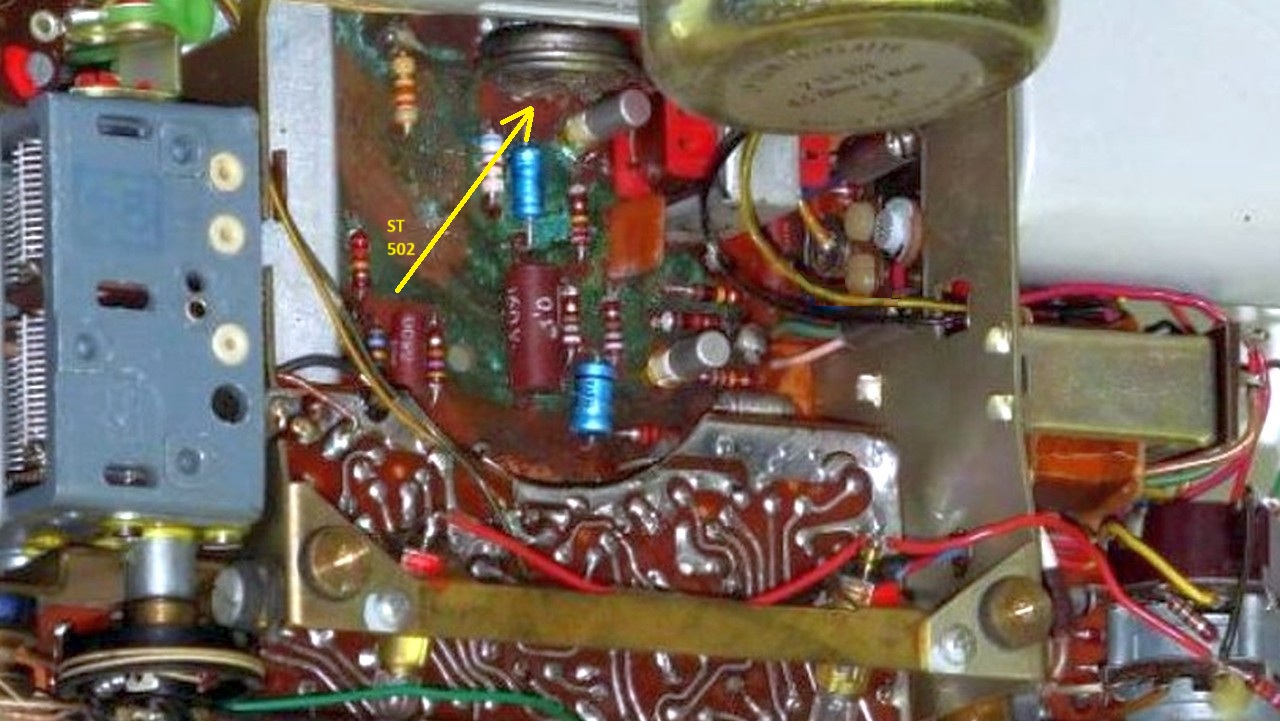
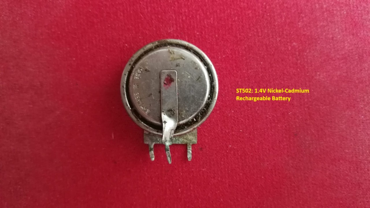
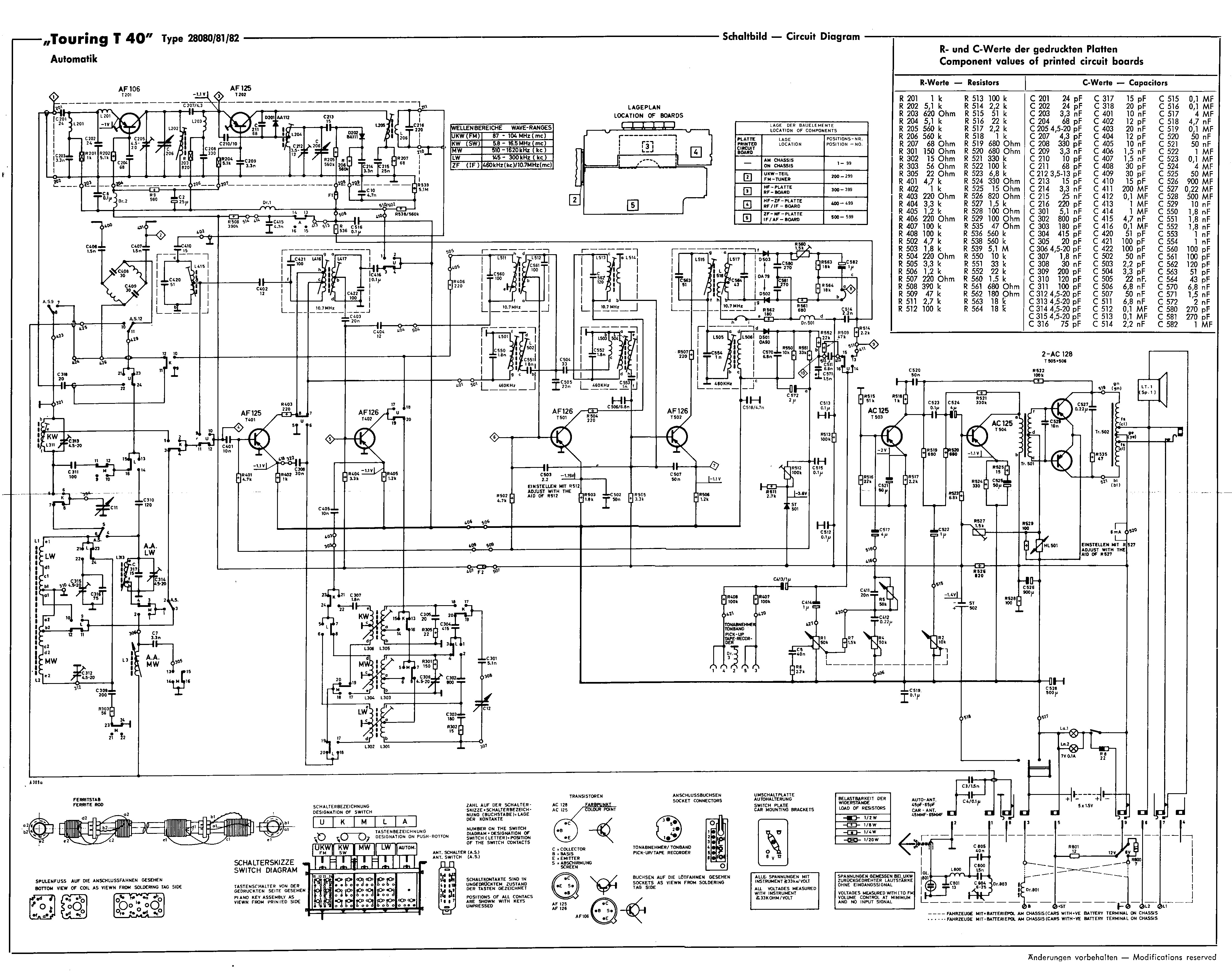
The Touring Automatik T40 was an expensive portable transistor radio built in the early 1960s by Standard Elektrik Lorenz in West Germany. The T40 was a battery-powered multi-band receiver that allowed listening to Medium Wave (510 - 1620 kHz), Long Wave (145 - 300 kHz), Short Wave (5.8 - 16.5 MHz) and Frequency Modulation (87 - 104 MHz). The radio used 10 germanium transistors: AF106, AF125, AF125, AF126, AF126, AC125, AC125, AC128, AC128 and 6 germanium, silicon and one selenium diodes: AA112, BA111, OA79, OA79, OA90, SN 693-5. The receiver circuit consisted of four interconnected printed circuit boards. The frequency range was changed via a five-button keyboard located at the top of the dial scale. The T40 had three antennas, one wound on a long ferrite core for OM and OL, one whip for SW and another whip for FM, both 31.496 in long. The intermediate frequencies were: 460 kHz for Amplitude Modulation and 10.7 MHz for FM. The dial scale was a linear type with separate indicator rods moved by a double system of cords and pulleys that acted separately depending on whether the FM button or one of the others (OL, AM, OC) was pressed. The fifth button (AUTOMATIK-AUS) was used to exclude the Automatic Frequency Control (AFC) in FM. The dial could be illuminated by two 7 V 0.1 A bulbs that could be activated by a specific button. The audio amplifier was a classic one, with drive and output transformers for the AC128 push pull that provided 1.8 W of power. The speaker was a 7x5 in elliptical with 4,5 Ohm impedance. A 1.4 V rechargeable Nickel-Cadmium DEAC type battery was soldered to the audio and FI board, which served to polarize the BF transistors and those used in the FM board. In addition to the volume control, which included the power switch, the T40 had separate controls for bass and treble. Power could be supplied by 5 x 1.5 V D-type batteries (for a total of 7.5 V) which were located in the battery compartment, or by a car battery via a special adapter which was inserted into the connector located on the left side of the pedestal under the battery compartment. The adapter included a switch to select 12 or 6 V depending on the car battery. The dimensions of the radio were: 11.8 x 7.4 x 3.7 inch, and the weight was 7 lb 7.8 oz without batteries. The initial price of this radio in 1963 was 362 DM, equivalent to 56,500 Lire, which is worth approximately 766 current Euros. © IK3HIA, 2025. |
|||||||
|
|
|||||||
 |
 |
 |
 |
||||
 |
 |
 |
 |
||||
|
La Touring Automatik T40 era una costosa radio portatile a transistor costruita all'inizio degli anni 60 dalla Standard Elektrik Lorenz nella Germania Ovest. La T40 era un ricevitore multigamma con alimentazione a batterie che permetteva l'ascolto delle Onde medie (510 - 1620 kHz), delle Onde Lunghe (145 - 300 kHz), delle Onde Corte (5,8 - 16,5 MHz) e della Frequenza Modulata (87 - 104 MHz). La radio utilizzava 10 transistor al germanio: AF106, AF125, AF125, AF126, AF126, AC125, AC125, AC128, AC128 e 6 diodi al germanio, al silicio e uno al selenio: AA112, BA111, OA79, OA79, OA90 e SN 693-5. Il circuito del ricevitore era formato da quattro schede a circuito stampato connesse tra loro. Il cambio gamma avveniva tramite una tastiera a cinque tasti posta in alto sulla scala parlante. La T40 disponeva di tre antenne, una avvolta su un lungo nucleo di ferrite per le OM e le OL, una a stilo per le OC e un'altra a stilo per la FM entrambe lunghe 80 cm. Le frequenze intermedie erano: 460 kHz per la Modulazione d'Ampiezza e 10,7 MHz per la FM. La scala parlante era del tipo lineare con asticelle indicatrici separate e mosse da un doppio sistema di cordicelle e carrucole che agiva separatamente a seconda se era premuto il tasto FM o uno degli altri (OL, AM, OC). Il quinto tasto (AUTOMATIK-AUS) serviva per escludere il Controllo Automatico di Frequenza (AFC) in FM. La scala parlante poteva essere illuminata da due lampadine da 7 V 0,1 A attivabili tramite apposito pulsante. L'amplificatore audio era un classico, con trasformatori di pilotaggio e di uscita per il push pull di AC128 che forniva 1,8 W di potenza. L'altoparlante era un ellittico da 13x18 cm con impedenza di 4,5 Ohm. Nella scheda audio e FI era saldata una pila ricaricabile al Nickel-Cadmio tipo DEAC da 1,4 V che serviva per la polarizzazione dei transistor di BF e di quelli utilizzati nella scheda FM. Oltre al controllo del volume, che comprendeva l'interruttore di accensione, la T40 era dotata di controlli separati per i toni bassi e gli acuti. L'alimentazione poteva essere fornita da 5 pile a torcia tipo D da 1,5 V (per un totale di 7,5 V) che trovavano posto nel vano portabatterie, oppure dalla batteria di un'auto tramite apposito adattatore da inserire nel connettore che si trovava nella parte sinistra del piedistallo sotto il vano portabatterie. L'adattatore comprendeva un deviatore per selezionare 12 o 6 V a seconda della batteria dell'auto. Le dimensioni della radio erano: 30 x 18,8 x 9,3 mm / 11.8 x 7.4 x 3.7 inch, e il peso era di 3.4 kg / 7 lb 7.8 oz senza batterie. Il prezzo iniziale nel 1963 di questa radio era di 362 DM, equivalenti a circa 56500 Lire, le quali valevano circa 766 euro attuali. © IK3HIA, 2025. |
|||||||
|
|
|||||||
 |
 |
 |
 |
||||
 |
 |
 |
 |
||||
|
Return to top of page
|
|||||||
|
The T40
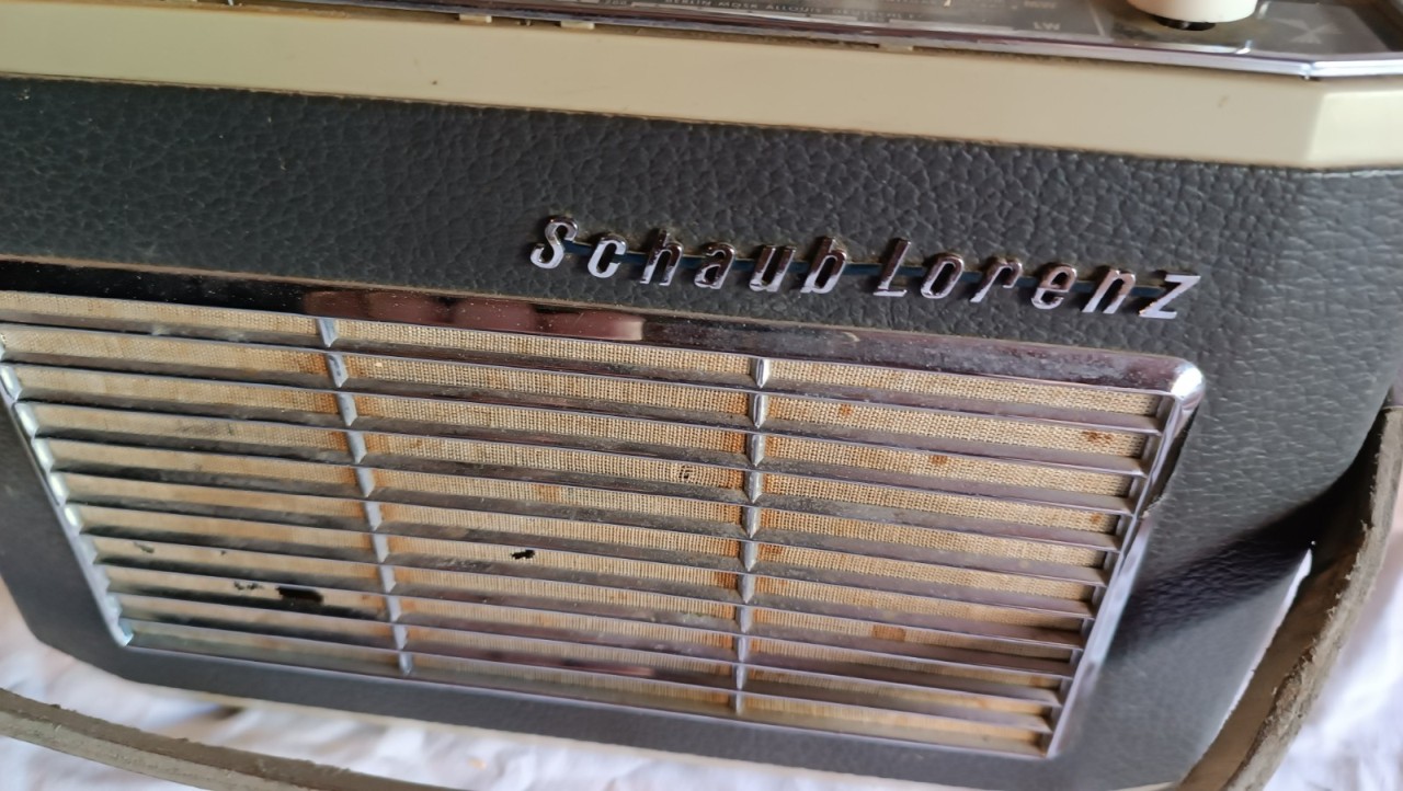
Automatik I got was in really bad shape. The cabinet was very dirty, the
grill cloth covering the speaker was stained and had holes in several
places, the tuning knob did not move the indicators and if the radio was
powered it did not show any signs of life. To finish
the restoration, all I had to do was clean the cabinet and replace the
perforated speaker grille cloth. I cleaned the cabinet using some
cleaning and disinfectant wipes stolen from my XYL's reserve. Then,
after having very carefully lifted the metal tabs that held the grille
to the cabinet, I proceeded to remove (scrape off) the old cloth and
replace it with a scrap of light beige fabric kindly provided by my
generous XYL. I cut and glued the cloth to the grille, stretching it as
best I could, and when the glue had dried I fixed it to the cabinet,
always closing the tabs with extreme caution.
|
|||||||
 |
 |
 |
 |
||||
 |
 |
 |
 |
||||
|
Return to top of
page
|
|||||||
|
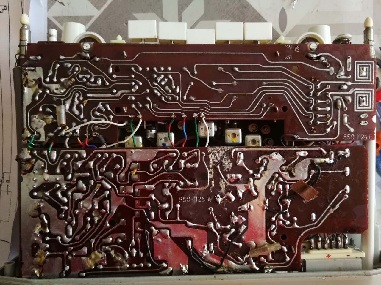
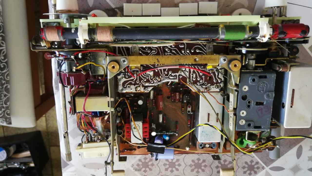
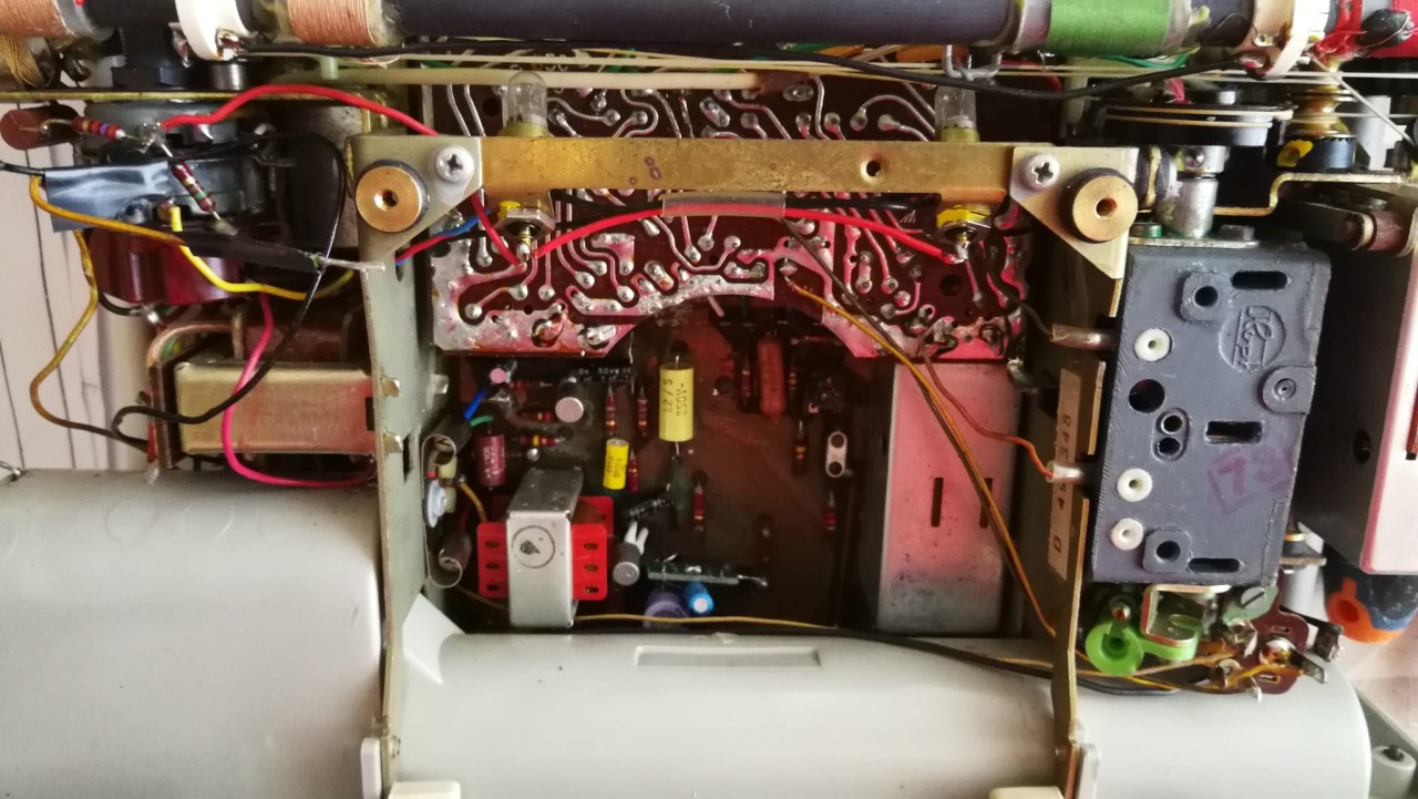
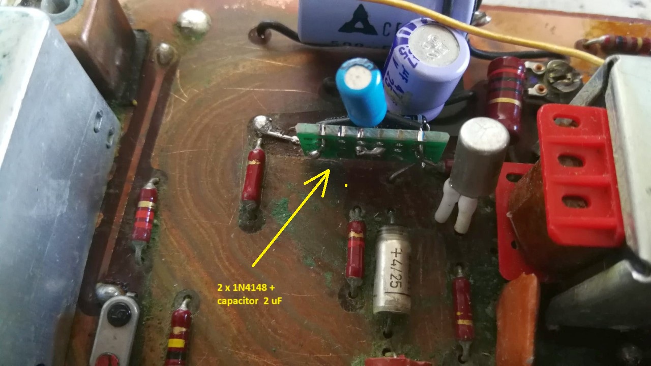
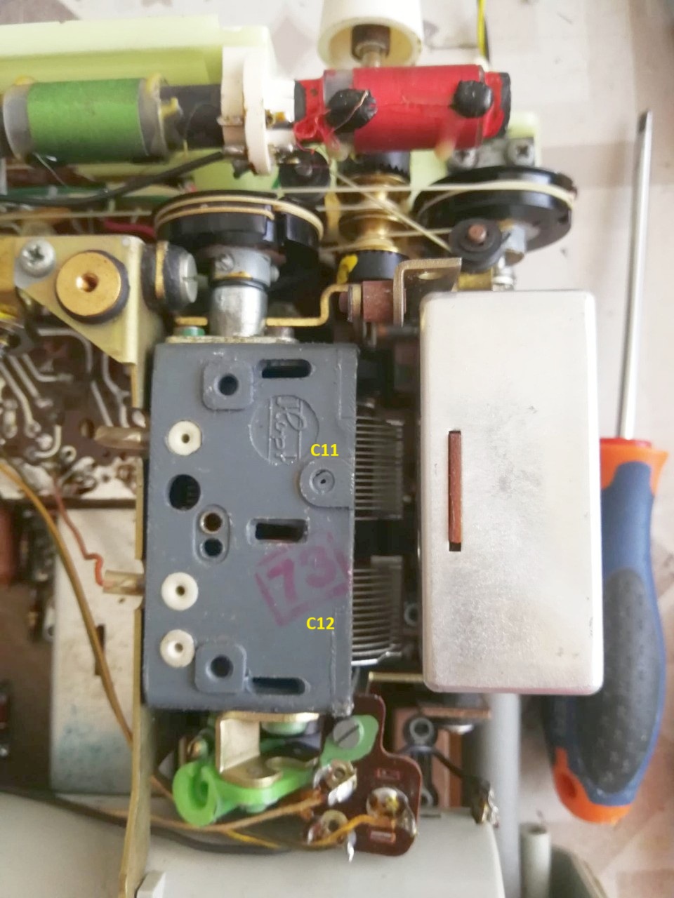
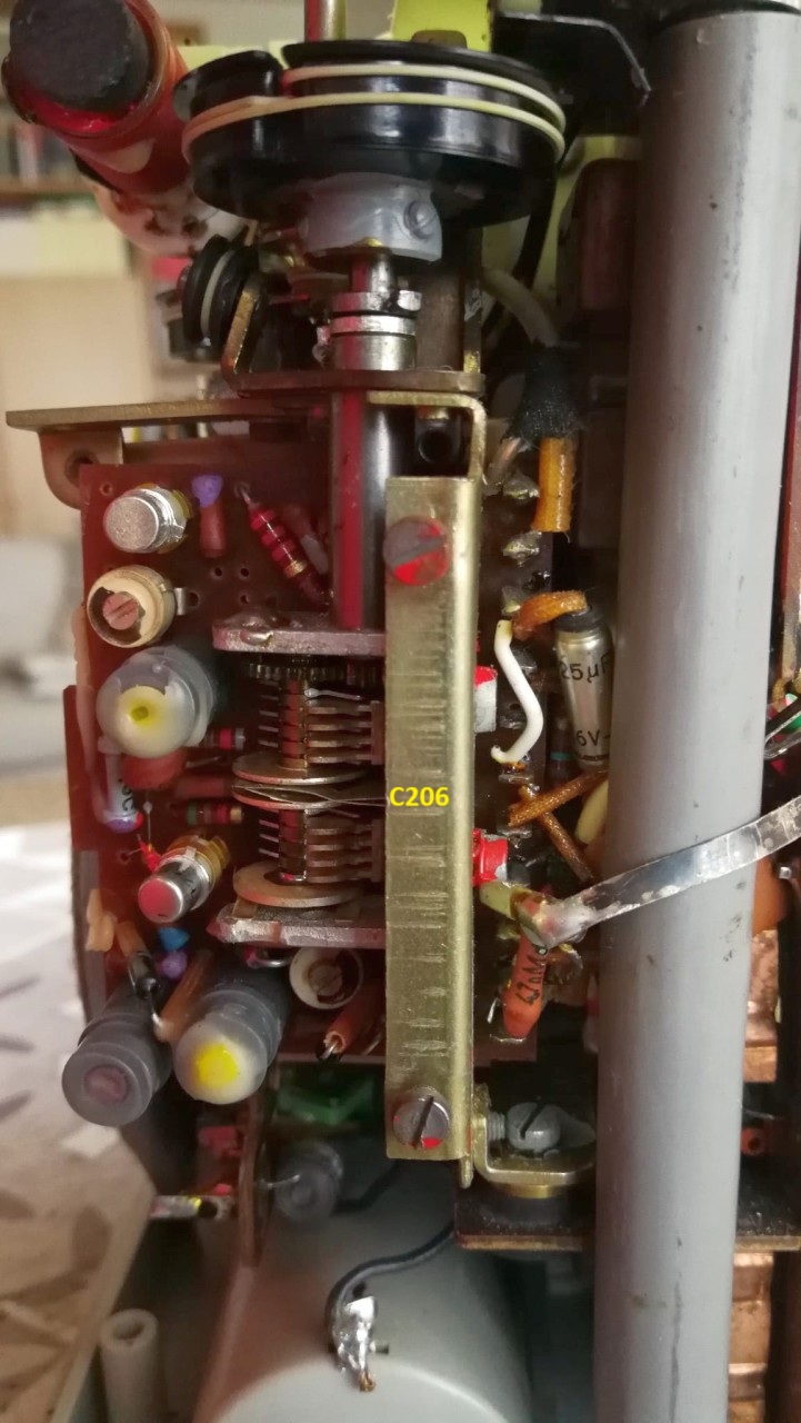
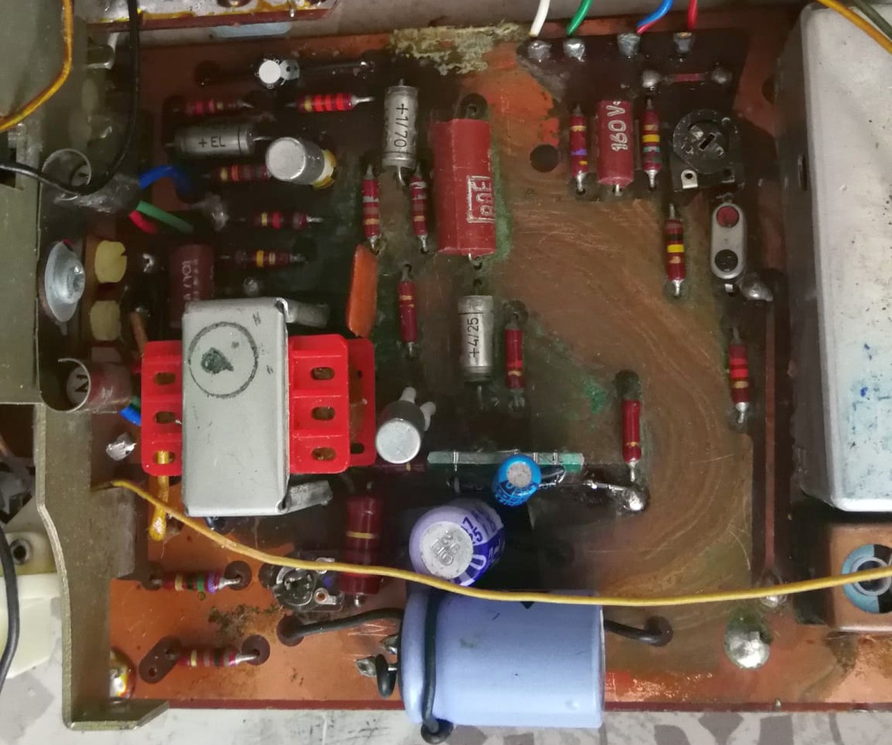
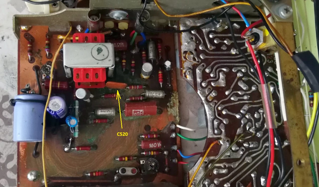
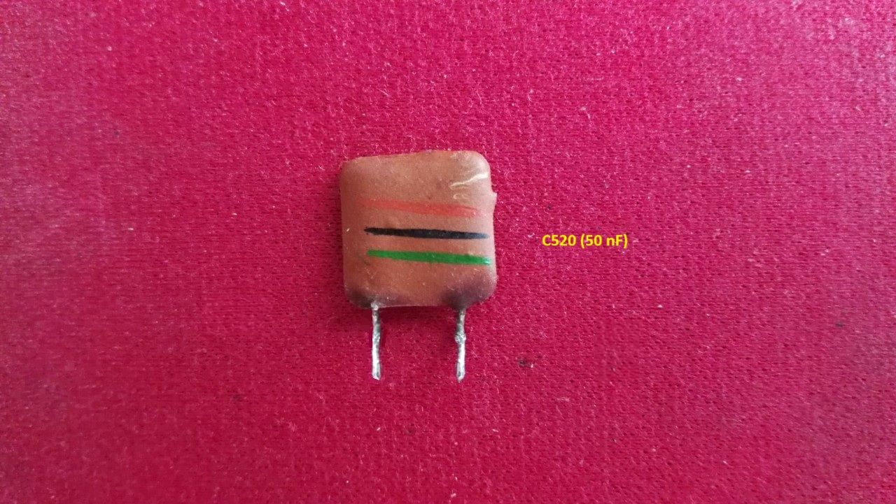
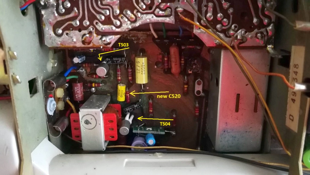
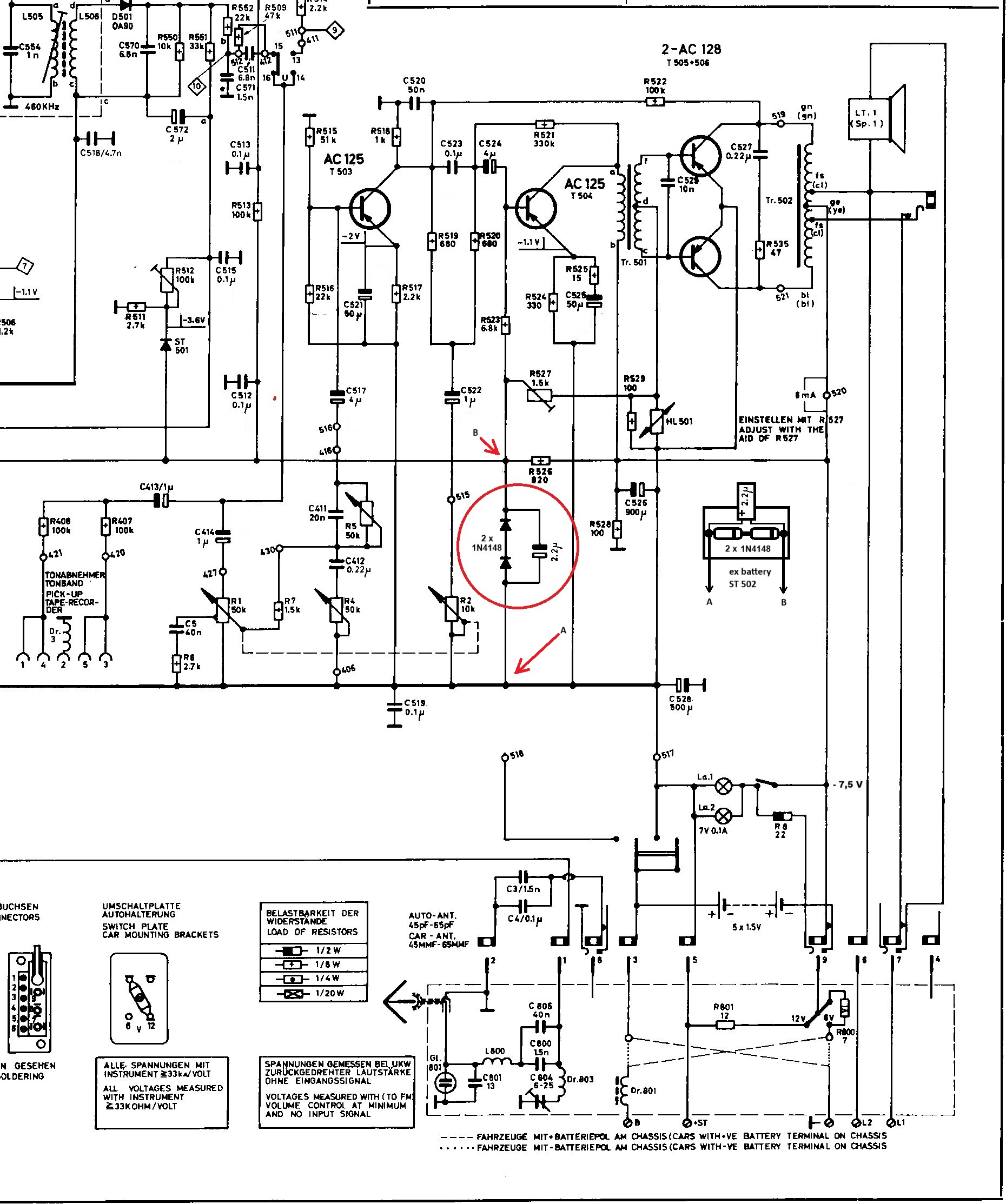
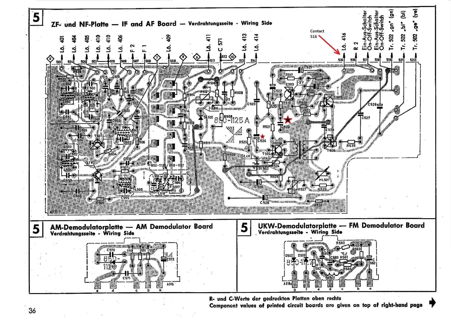
L'esemplare di T40 Automatik di cui sono venuto in possesso era ridotto piuttosto male. II mobiletto era molto sporco, la tela della griglia che copriva l'altoparlante era macchiata e bucata in più punti, la manopola di sintonia non faceva muovere gli indicatori e se la radio veniva alimentata non dava alcun segno di vita. Cercando in internet mi sono subito imbattuto nell'ottimo sito del forum "Elettroni al Tramonto" nel quale molti appassionati collezionisti riparatori si scambiano informazioni sulle apparecchiature che restaurano. Il T40 risultava affetto da un noto problema: l'azione distruttiva della pila al nickel cadmio saldata sulla scheda Audio, e utilizzata per la polarizzazione dei transistor. La batteria al nickel cadmio era ricaricabile, veniva inserita nel circuito quando la radio era alimentata, ma i progettisti tedeschi non avevano pensato ai guai che tale pila avrebbe causato dopo vari anni di utilizzo. Probabilmente l'idea era che dopo un tot di tempo la radio doveva obbligatoriamente essere portata in un centro di riparazioni dove i tecnici avrebbero preventivamente sostituito la pila con una nuova. Ma le istruzioni sono fatte per non venire rispettate e la pila originale rimaneva saldata per sempre sul circuito stampato esaurendosi lentamente. Dopo alcuni anni infatti la pila si esauriva del tutto, l'involucro metallico si gonfiava, si crepava e il contenuto acido si spandeva sul circuito stampato corrodendone il rame (il circuito era a doppia faccia, con tracce ramate su ambo i lati) e i componenti installati rendendo la radio inutilizzabile. Questa distruzione era ben visibile nell'esemplare che volevo riportare in vita. La soluzione era semplice, la pila incriminata poteva venire sostituita da due diodi al silicio tipo 1N4148 posti in serie tra loro con in parallelo un condensatore elettrolitico da 2,5 µF (vedi schema e Foto 022). La caduta di tensione sui due diodi in serie era di circa 1,4 V simile perciò alla tensione della pila, e naturalmente i due diodi non avrebbero causato fenomeni di corrosione. Il problema era che tutte le piste ramate della faccia dov'era saldata la pila erano state corrose, e anche alcune resistenze, alcuni condensatori e gli zoccoletti dei transistor T503 e T504 erano danneggiati. Dopo aver dissaldato la vecchia pila ho provveduto a ripulire lo stampato usando abbondantemente dell'alcool etilico denaturato, a rifare i collegamenti corrosi con dei fili saldati sulla faccia opposta dello stampato, a sostituire quei condensatori e resistenze che presentavano visibili segni di corrosione e a saldare direttamente al circuito i transistor T503 e T504. Dopo le sostituzioni ho alimentato la radio con un alimentatore stabilizzato regolato a 7 V, ho selezionando la gamma FM e ho provato ad accenderla. La T40 è tornata in vita, dall'altoparlante sono usciti dei suoni e il volume era regolabile, ma non ho potuto sintonizzare bene la stazione perché la manopola di sintonia non agiva. Le cordicelle e le pulegge del sistema di sintonia erano a posto, i problema era causato dagli assi dei condensatori variabili C206, C11 e C12 che erano bloccati. Probabilmente la radio era rimasta inutilizzata per così tanti anni che il grasso con cui erano stati lubrificati gli assi si era solidificato bloccando tutto. Ho risolto il problema senza smontare niente, a parte la copertura di alluminio della scheda FM, ho utilizzato lo spray pulisci contatti e un pennellino sottile per far penetrare il liquido detergente nelle bronzine e nei cuscinetti degli assi. Dopo un po' di tentativi, per merito dello spray e azionando la manopola di sintonia i variabili hanno iniziato a ruotare liberamente. Ho atteso che si asciugasse il detergente spay e ho lubrificato tutti i punti di rotazione con qualche goccia dell'olio della macchina da cucire della mia XYL. Una volta riaccesa la radio ho potuto sintonizzare varie stazioni, sia in FM che in OM, dall'altoparlante però uscivano voci e musica assieme a continue e fragorose scariche. La pazienza non mi manca, ma posso assicurare che ce n'è voluta veramente tanta per venire a capo del problema delle scariche. Come prima azione ho sostituito i rimanenti condensatori elettrolitici sulla scheda Audio ma non ho risolto il problema. Allora ho iniziato a sezionare i circuiti per individuare quello incriminato. Staccando il filo collegato al contatto 516 della scheda Audio, dall'altoparlante la musica e la voce spariva ma le scariche continuavano, perciò il problema era proprio nello stadio di Bassa Frequenza. A questo punto ho separato gli stadi di preamplificazione audio, transistor T503 e T504, e staccando il condensatore elettrolitico (nuovo) C524 le scariche sono completamente sparite, perciò il guasto era sicuramente nel circuito relativo al transistor T503, un AC125. Ricollegato il C524 ho staccato il C523, le scariche sono diminuite ma non scomparse del tutto e il suono risultava distorto. A ogni buon conto ho sostituito il C523 (0,1 µF) e ho staccato e sostituito il C520 (un condensatore quadrato piatto da 50 nF). Con la sostituzione del C520 le scariche sono completamente scomparse e finalmente il T40 è tornato a funzionare correttamente. Per terminare il restauro non mi rimaneva che ripulire il mobiletto e sostituire la tela bucata della griglia dell'altoparlante. Il mobile l'ho pulito utilizzando delle salviette detergenti e disinfettanti rubandole dalla riserva della mia XYL. Poi, dopo aver sollevato con estrema attenzione le linguette metalliche che fissavano la griglia al mobiletto, ho provveduto a togliere (raschiare via) la vecchia tela e a rimpiazzarla con un ritaglio di stoffa beige chiaro gentilmente procurato dalla mia generosa XYL. Ho ritagliato e incollato la tela alla griglia tendendola al meglio delle mie possibilità, e quando il collante si è asciugato l'ho fissata al mobiletto chiudendo sempre con estrema cautela le linguette. Visto che la radio era aperta, ho usato lo spray pulisci contatti sulla tastiera del cambio gamma e in qualche modo anche sul potenziometro del volume (non ci sono forellini in cui infilare la cannuccia, solo alcune strette fessure). La T40 sintonizza bene in tutte le gamme pertanto ho preferito non effettuare nessuna taratura anche per non rischiare di rompere qualche nucleo di ferrite che sono tutti bloccati con un collante. Il suono è abbastanza soddisfacente con qualche problema se vengono esaltati al massimo i toni bassi, inconveniente che ho riscontrato anche in altre radio tedesche dell'epoca. © IK3HIA, 2025 |
|||||||
 |
 |
 |
 |
||||
 |
 |
 |
 |
||||
|
Return to top of
page
|
|||||||
|
|
Return to: IK3HIA home page |
|
Return to: Transistor Radio |
|
Go to: Transistor diagrams |