 |
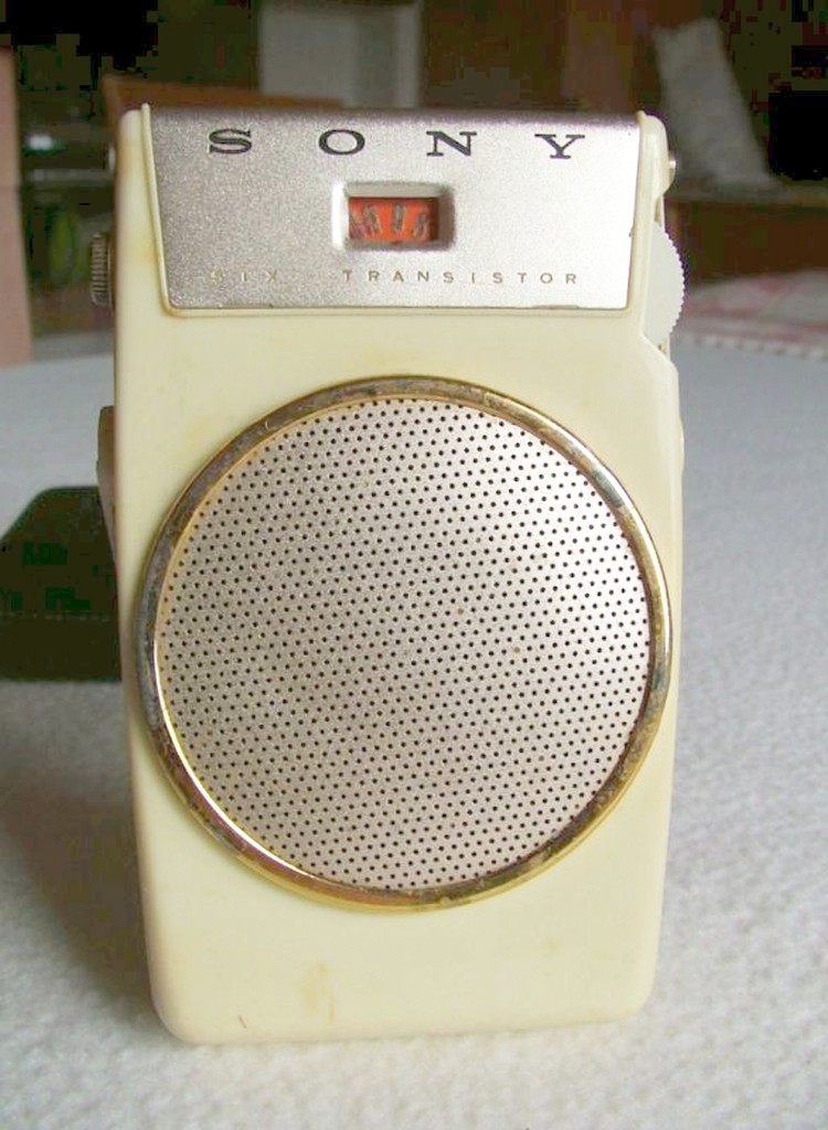
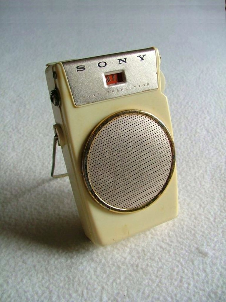
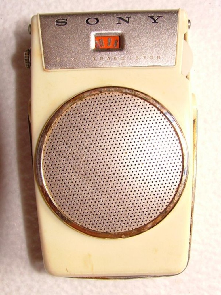
SONY
TR-610 Japan - 1958 |
|
|
|
SONY
TR-610 Japan - 1958 |
|
| |
 |
 |
Italiano
Riparazione |
||||
|
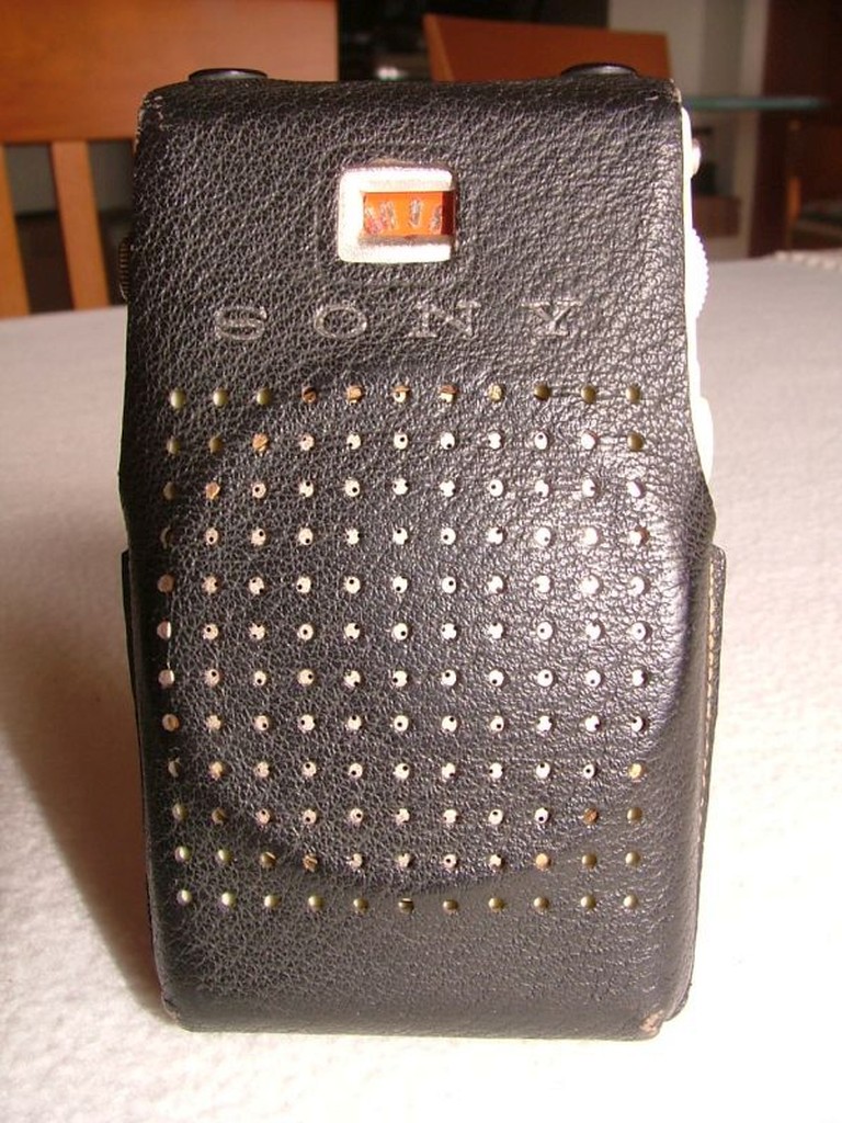
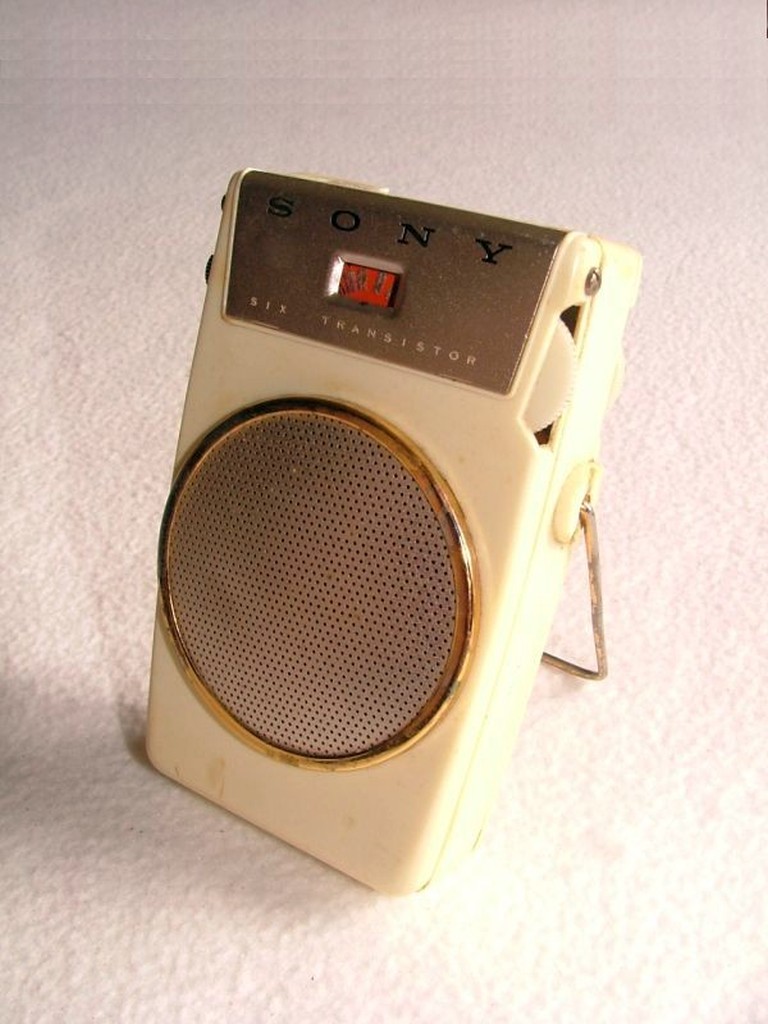
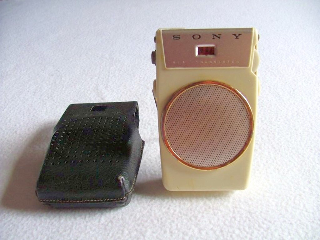
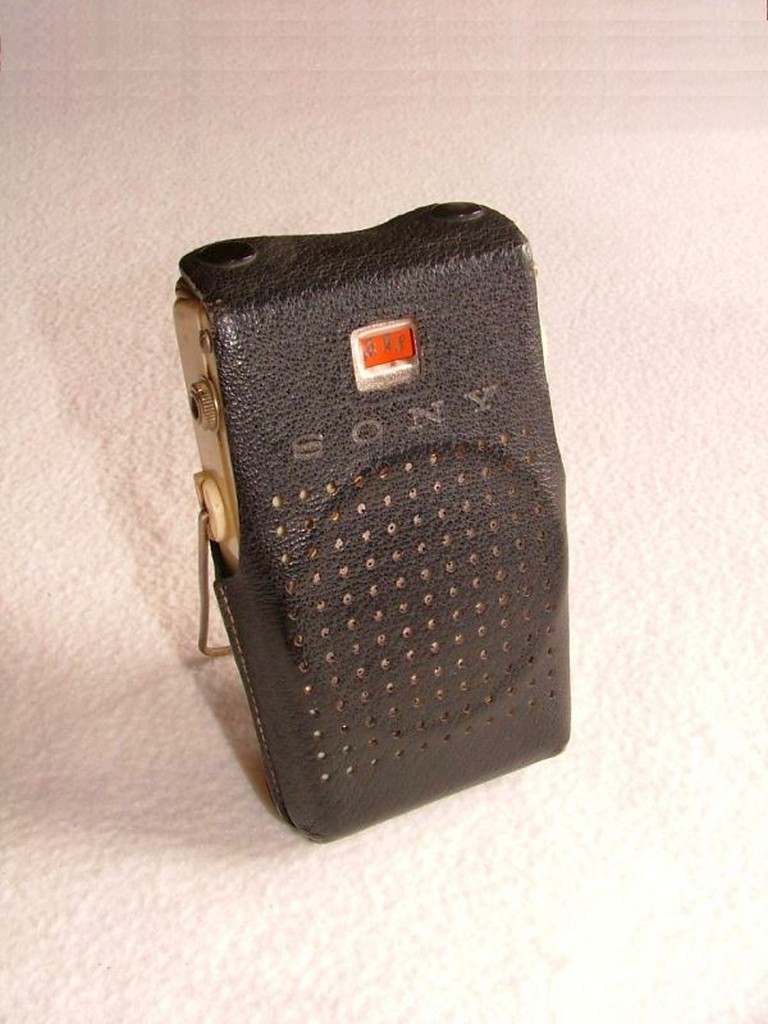
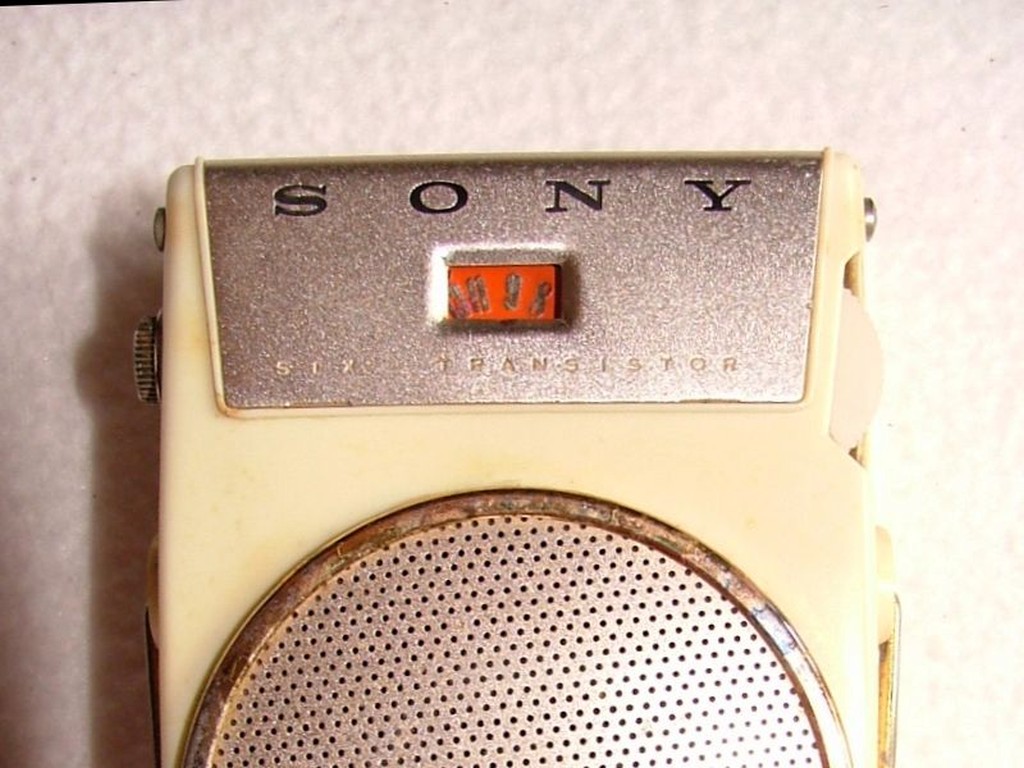
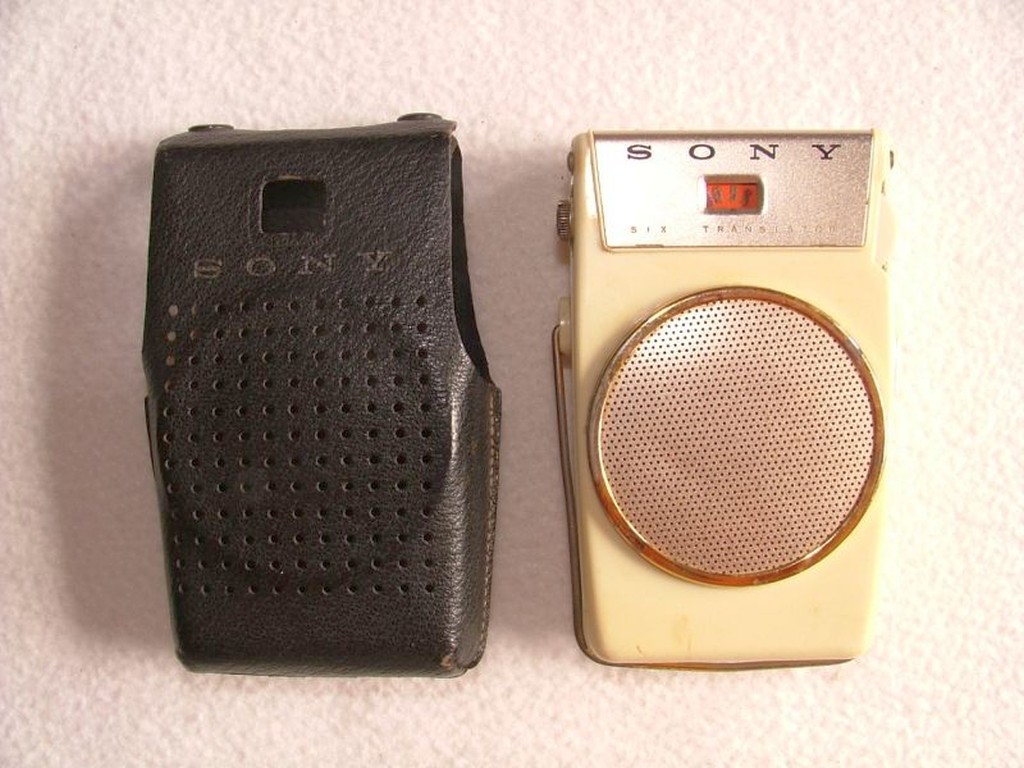
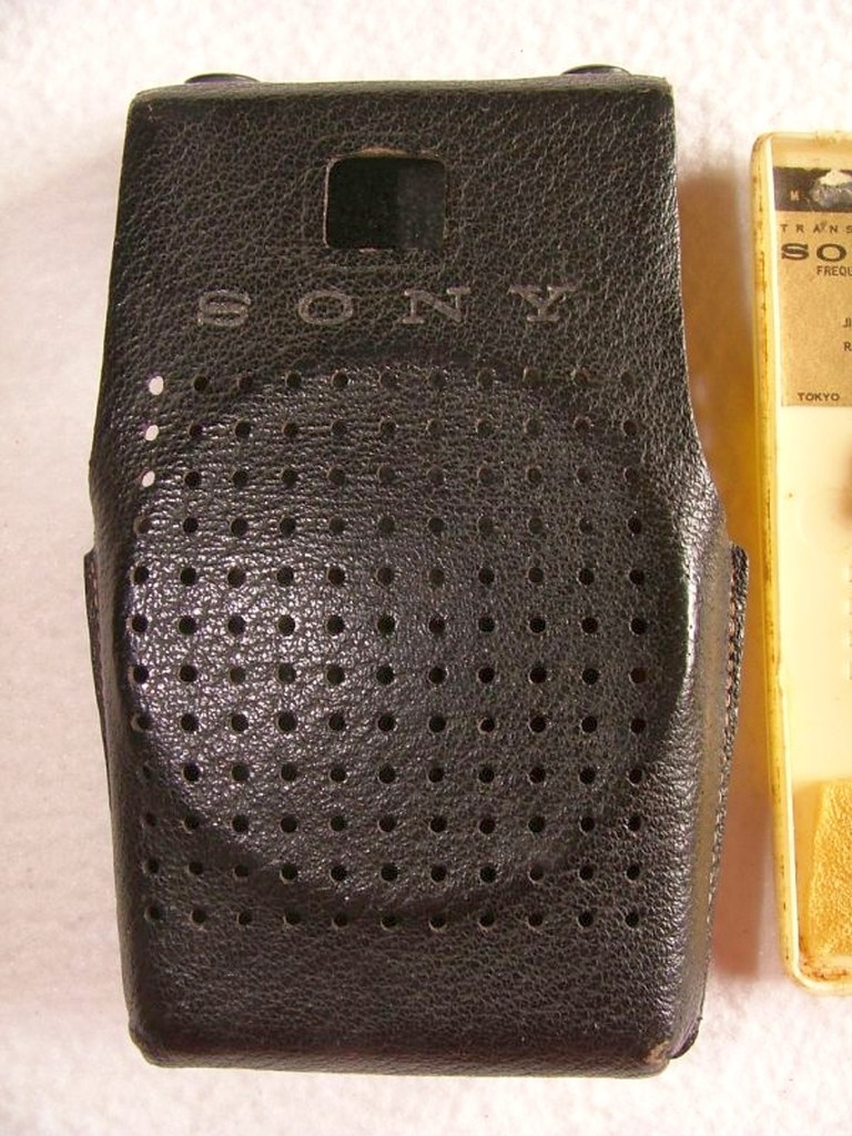
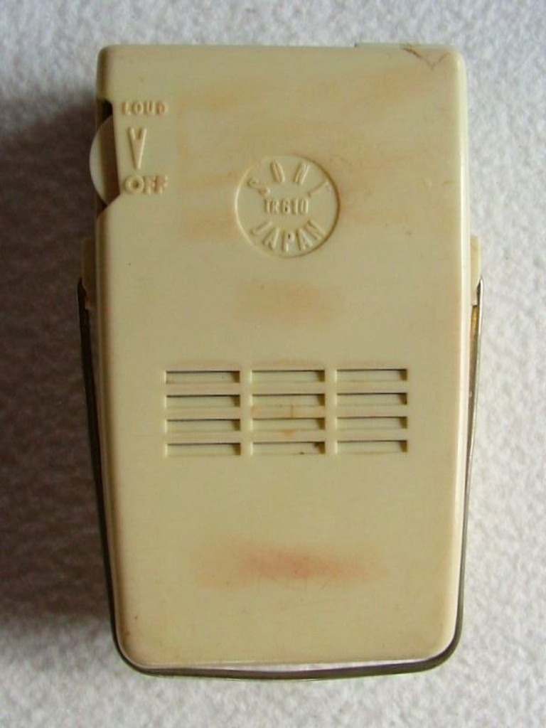
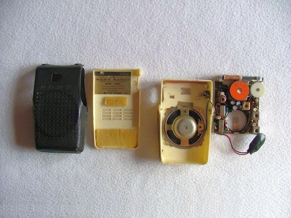
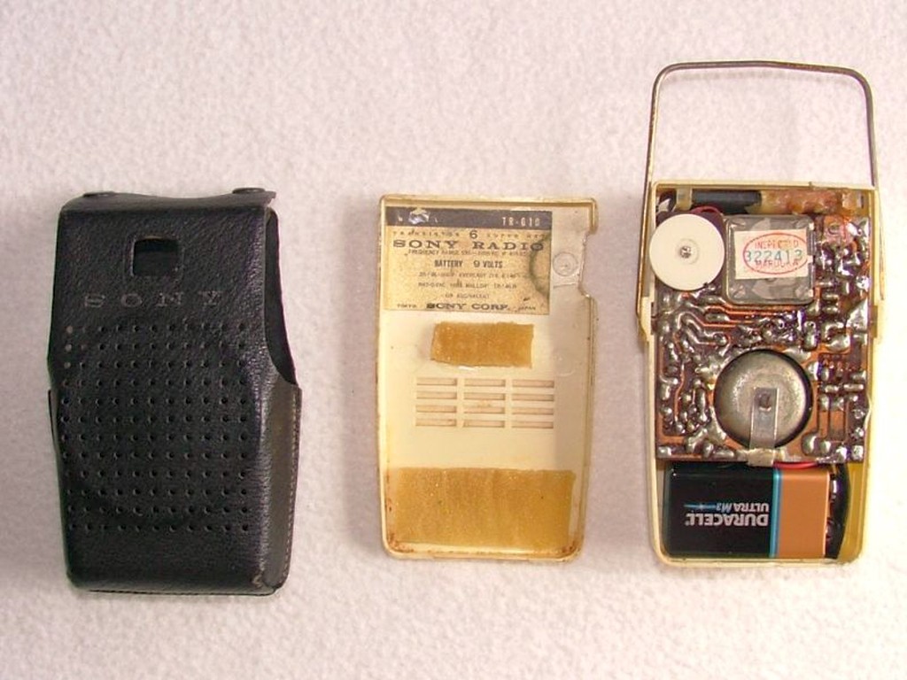
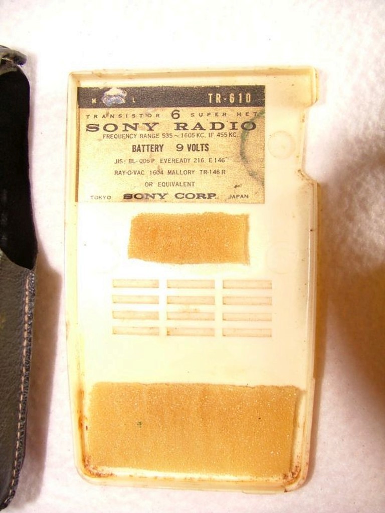
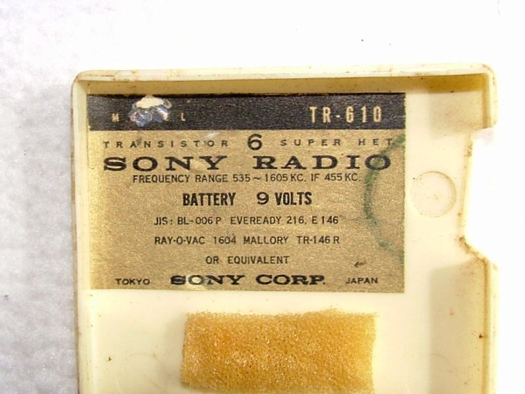
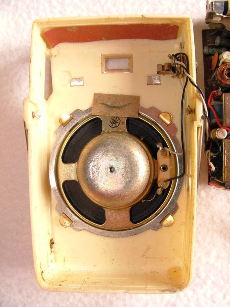
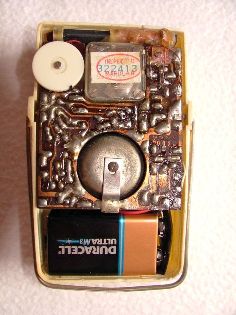
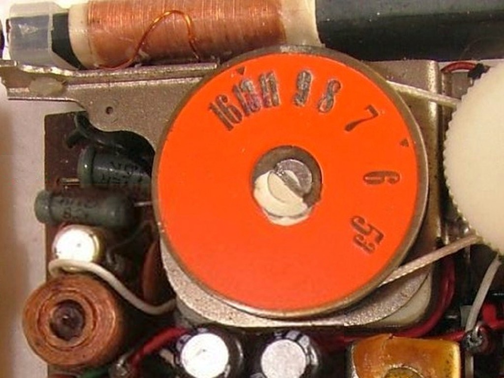
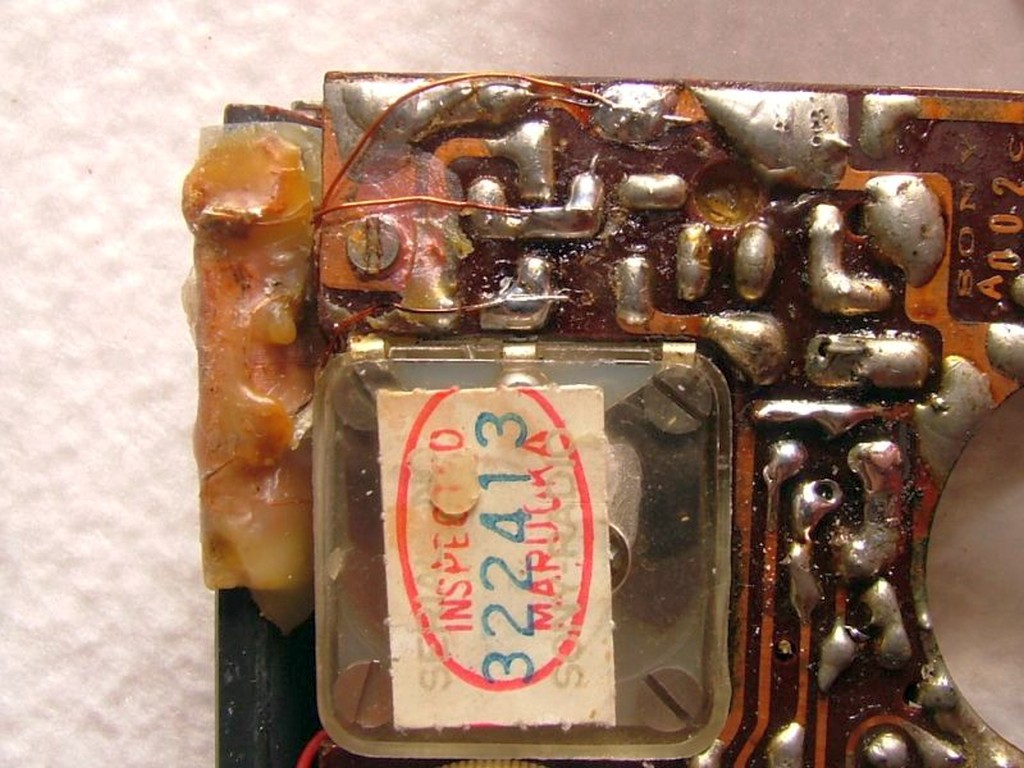
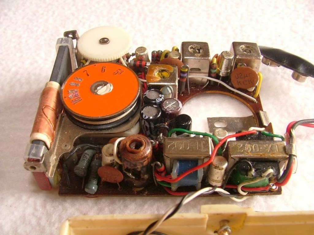
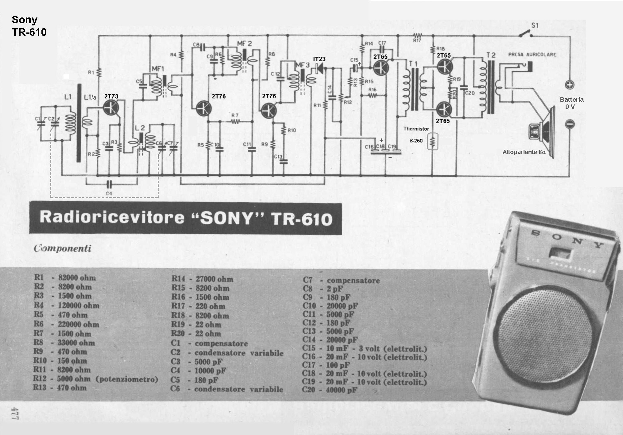
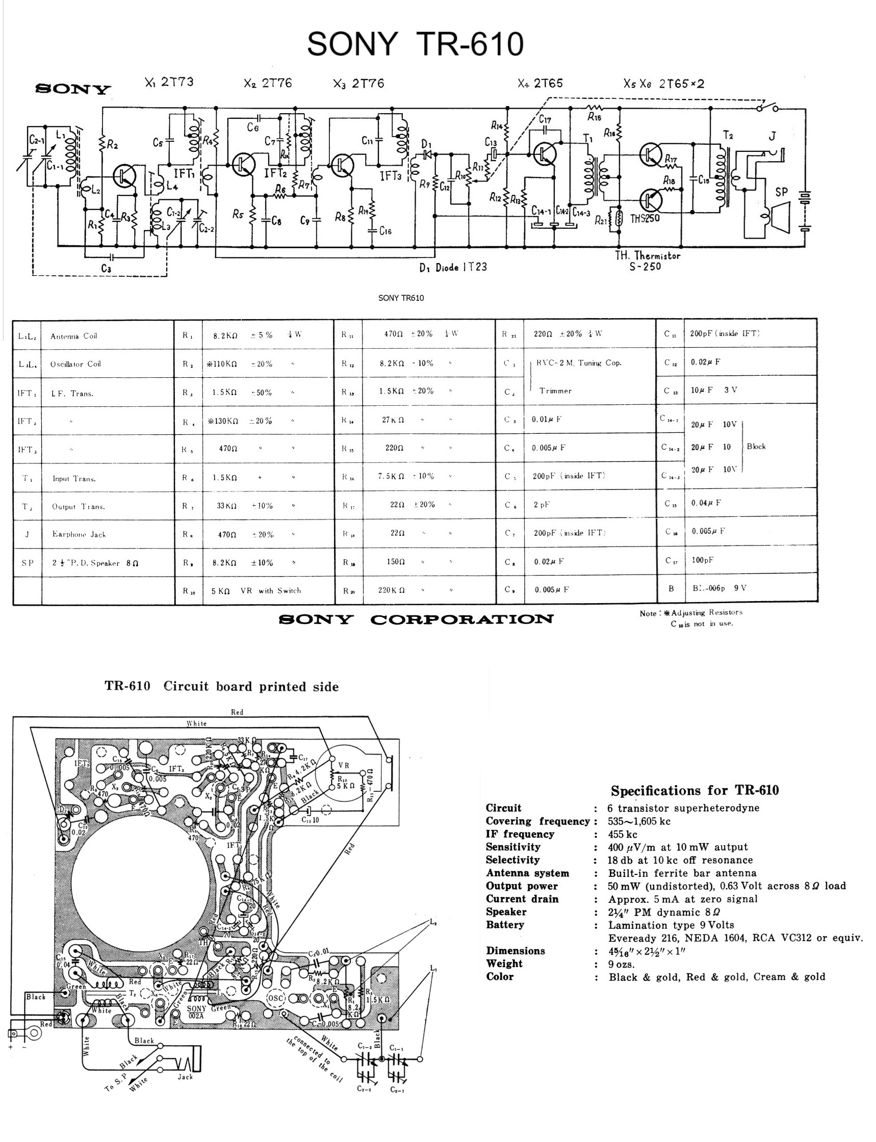
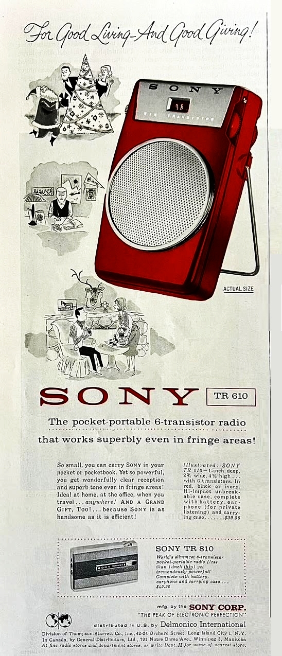
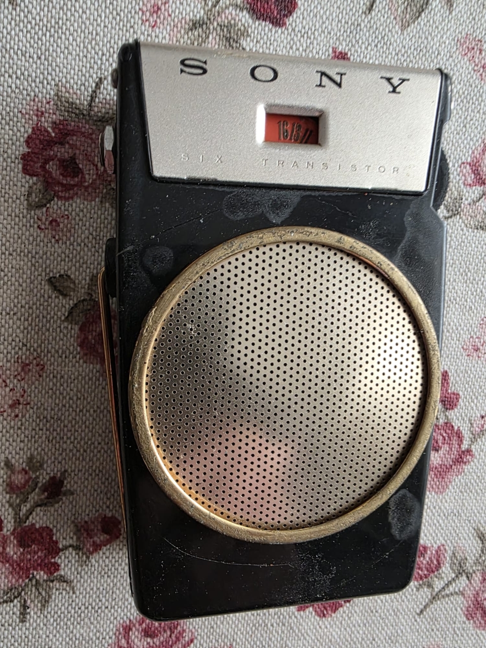
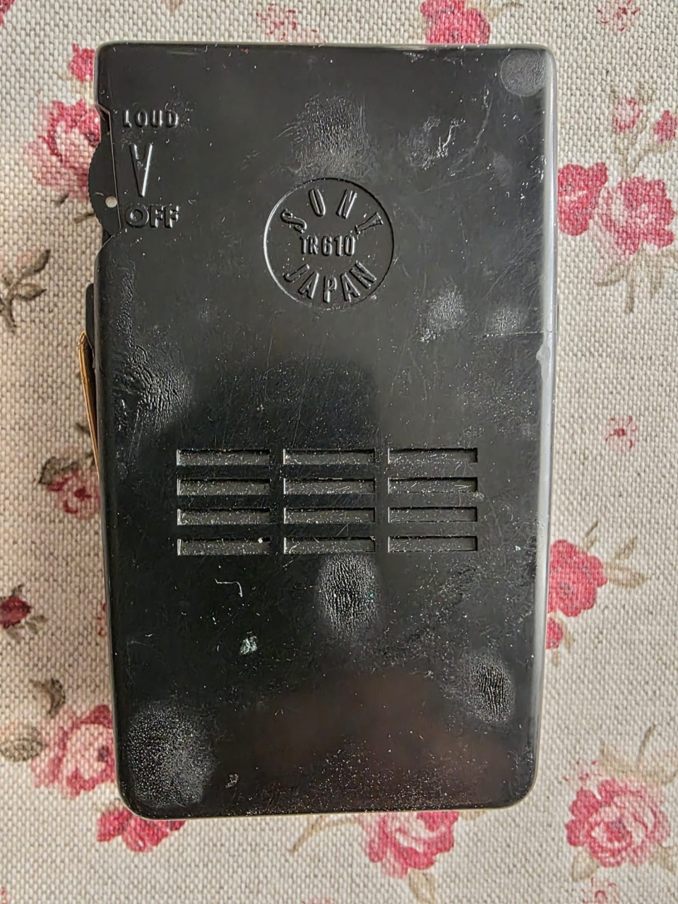
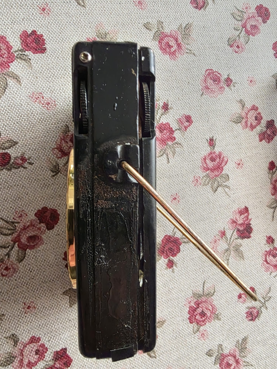
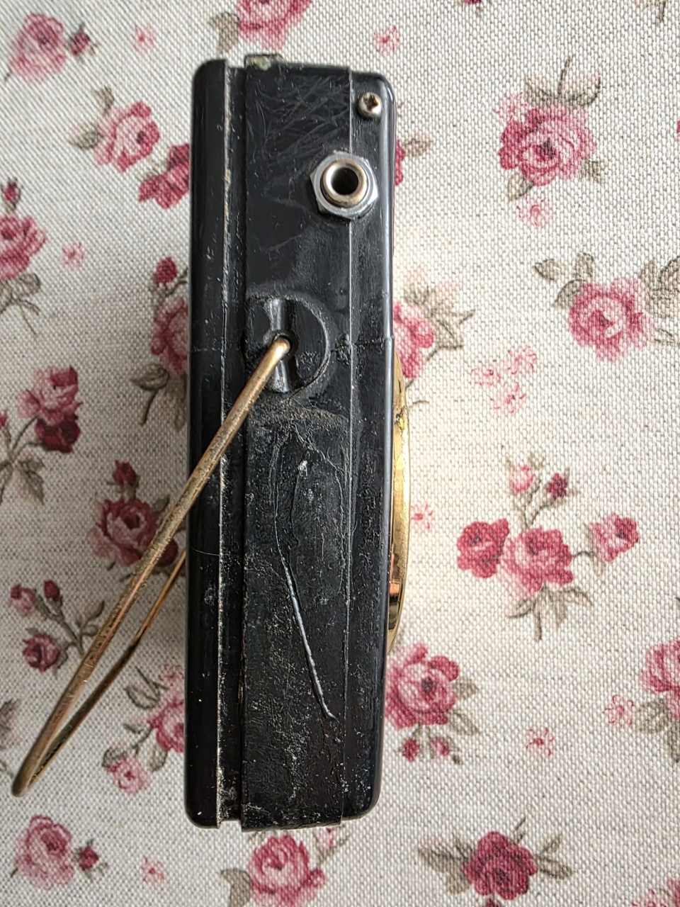
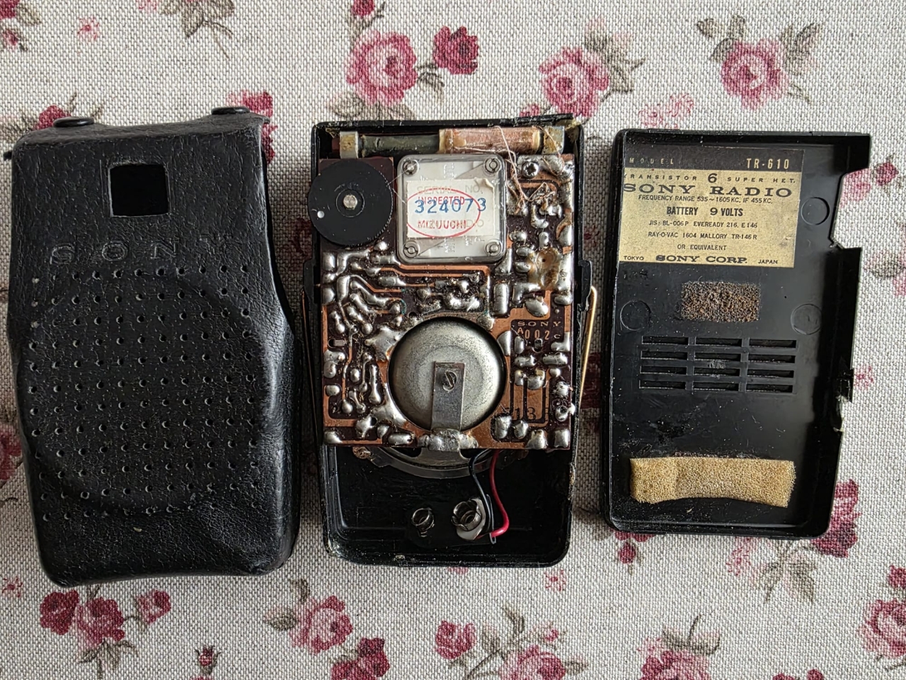
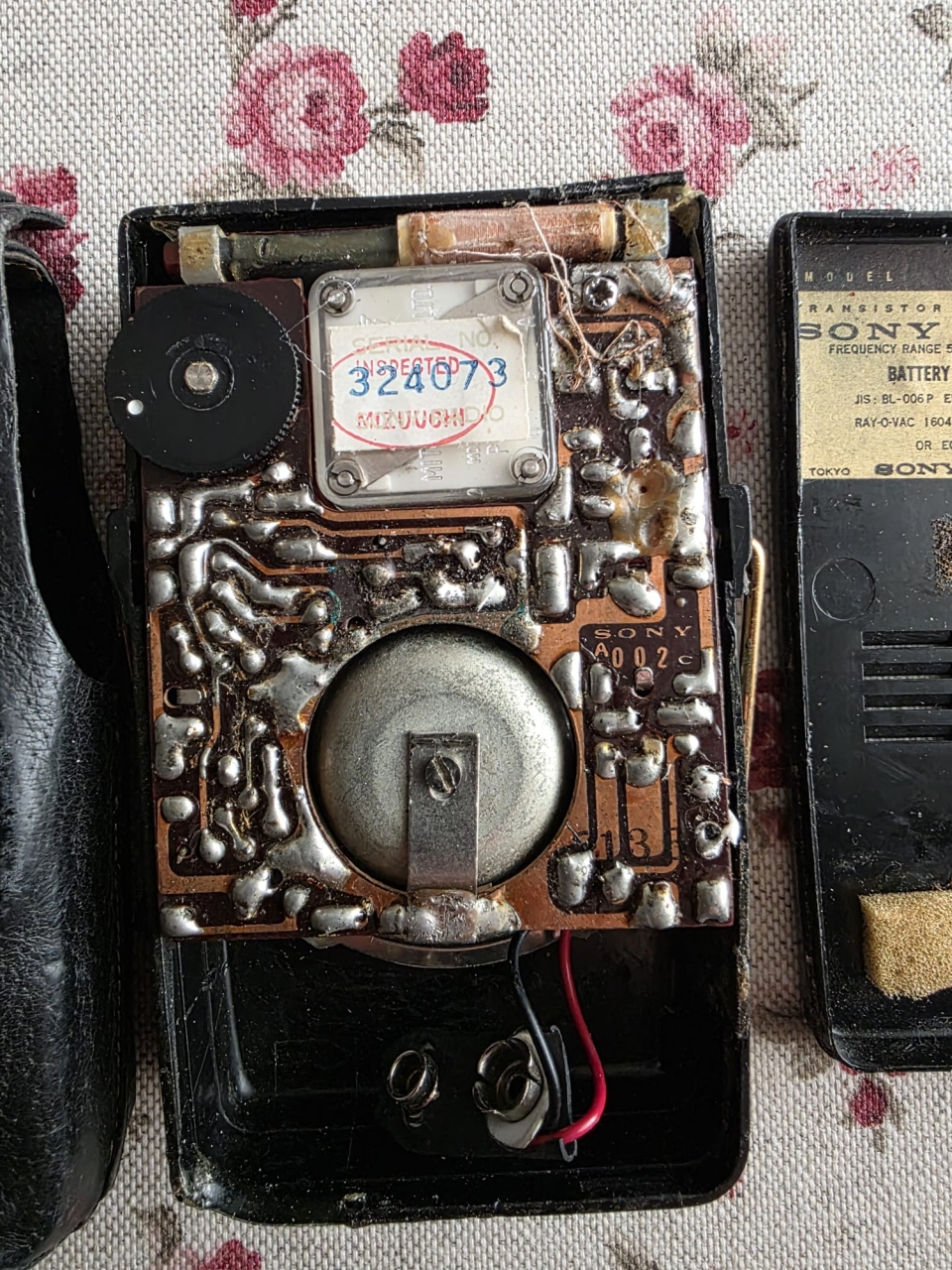
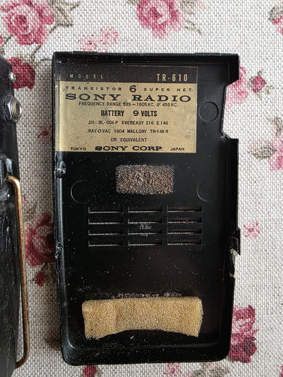
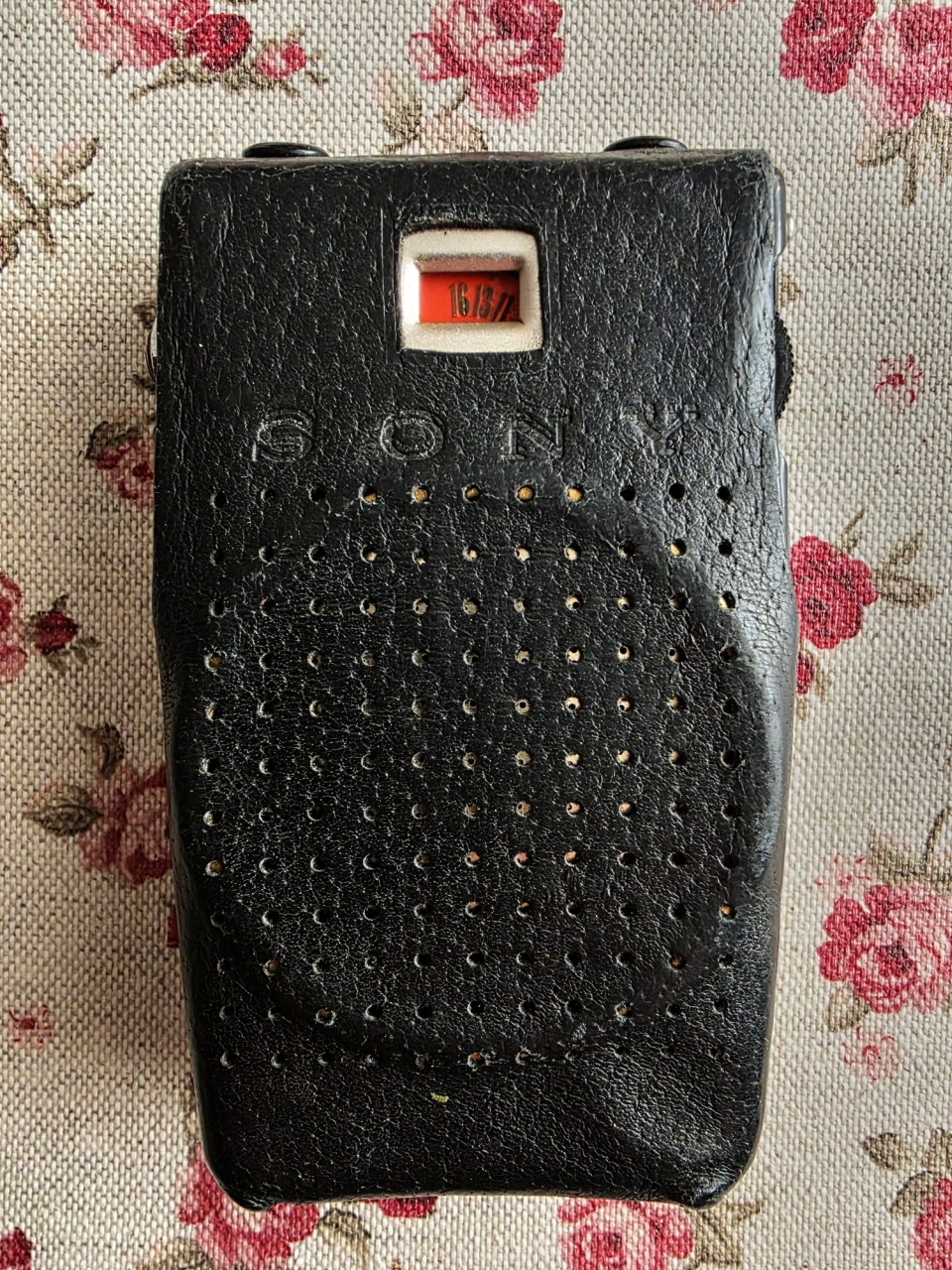
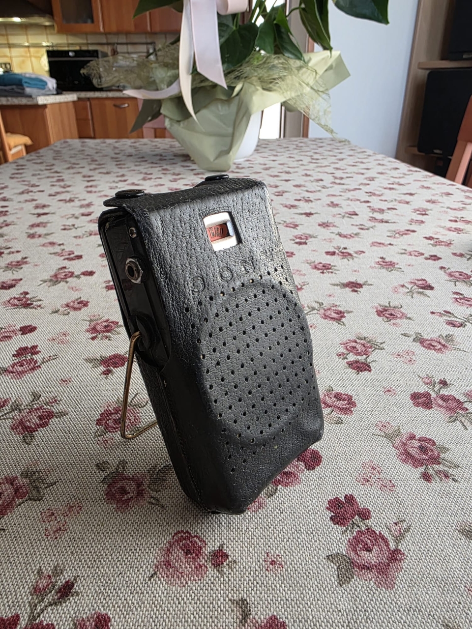
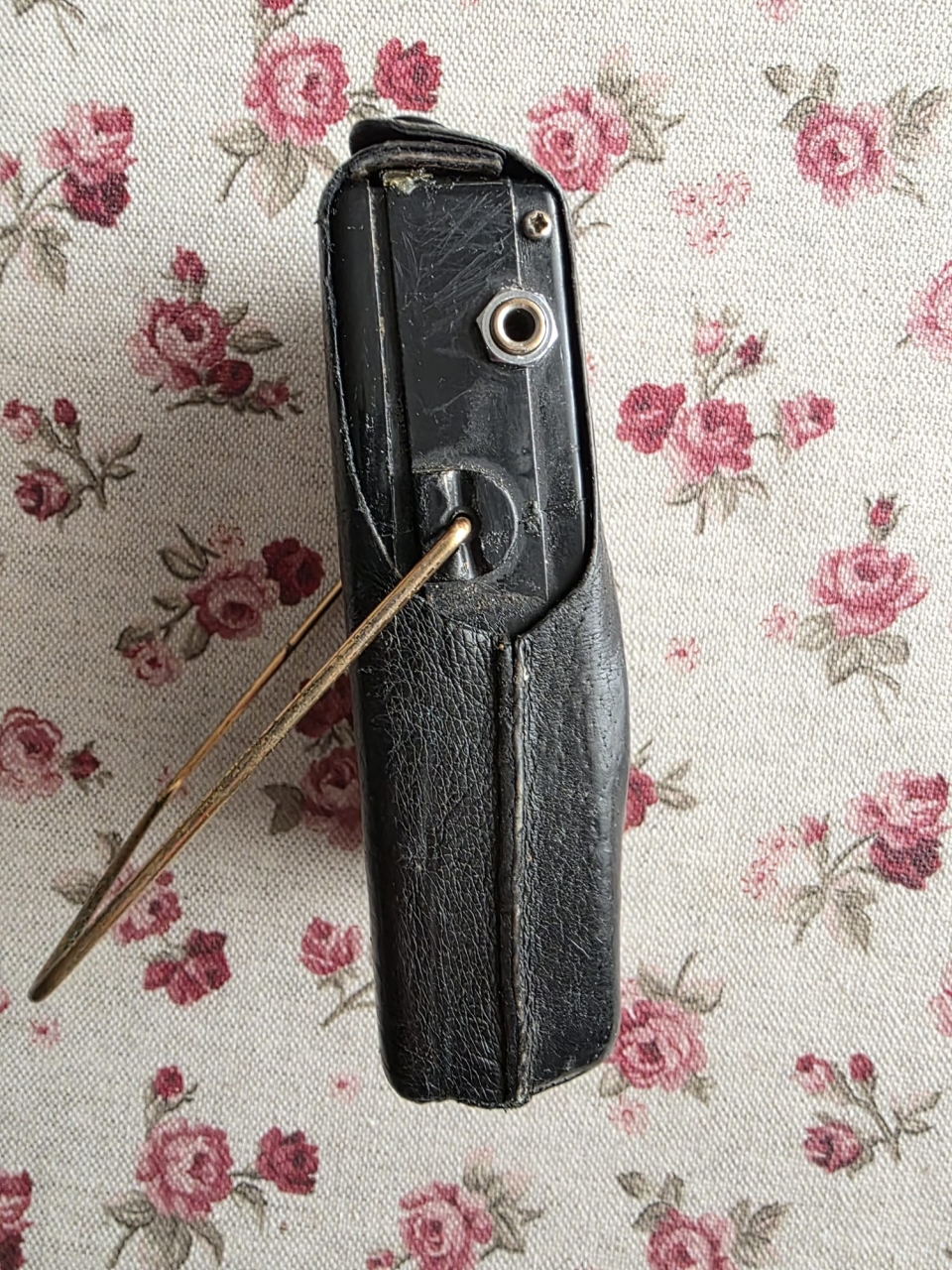
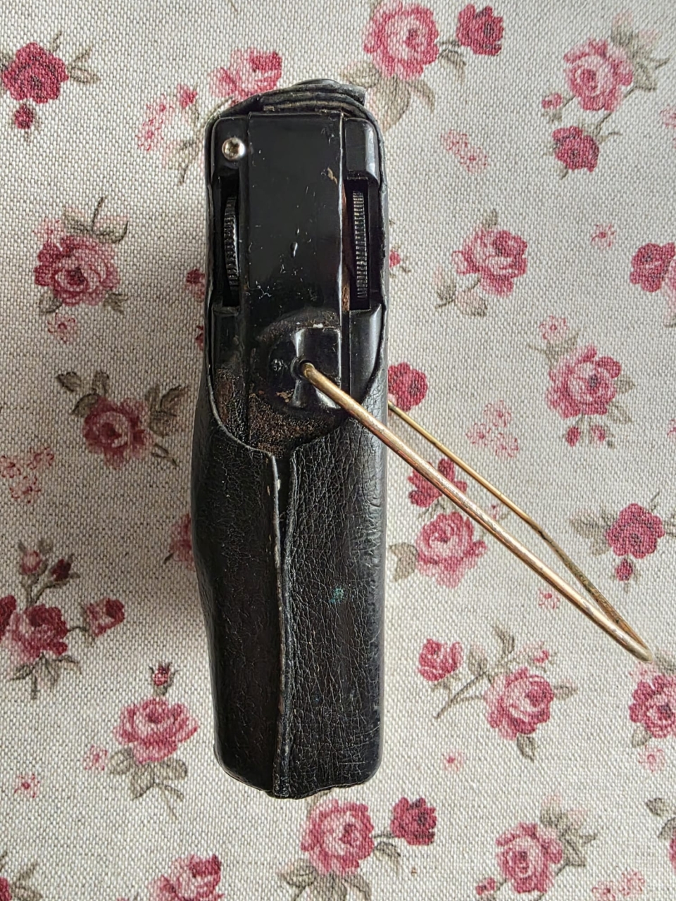
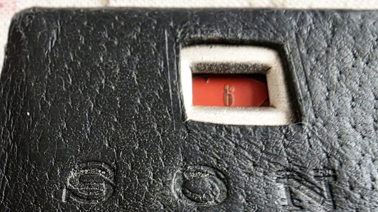
The TR-610 produced in Japan in the late 1950s was probably the first truly portable pocket radio with Medium Wave reception. The Sony radio was the reference prototype imitated by hundreds of manufacturing companies worldwide who would later replicate thousands of examples, similar in both appearance and technology. The TR-610 cabinet had a vertical format, with rounded shape and edges so that it could fit into the pocket of a shirt or jacket without getting caught, it was made of plastic with a metal speaker grill and a foldable metal bracket that once extracted allowed the radio to be placed in a vertical position on the shelf of a piece of furniture. The TR-610 was sold with a leather case and earphones. The circuit was a superheterodyne that used 6 germanium transistors produced by Sony: 2T73, 2T76, 2T76, 2T65, 2T65, 2T65 and a 1T23 diode. The frequency coverage was from 535 to 1605 KHz, and the Intermediate Frequency resonated at 455 KHz. The 8 Ohm speaker had a diameter of 2.25 inch. The power supply needed a 9 V battery type 6F22. The dimensions of the radio were: 2.5 x 4.2 x 1 inch, and the weight was 10.6 oz. Having to market the product in the U.S.A., the Japanese had taken care to insert two small triangles on the dial scale of the TR-610 corresponding to the two frequencies of the CONELRAD atomic warning system that had been adopted in the United States at the beginning of the Cold War with the U.S.S.R. (Further information by clicking here). On this page you can see some photos of the TR-610 serial number 322413 in my possession, and the description of the work I carried out to restore it so that it could become part of my collection of working transistor radios. **** I restored another TR610 in late 2025. It has serial number 324073 and a black cabinet. The only work I had to do during the restoration was replace the four electrolytic capacitors. At the top of the page, I've included a short video that demonstrates its excellent performance almost seventy years after its construction. IK3HIA © 2007 - 2026. |
|||||||
|
|
|||||||
 |
 |
 |
 |
||||
 |
 |
 |
 |
||||
|
|
|||||||
|
La TR-610 prodotta in Giappone sul finire degli anni '50 è stata probabilmente la prima radio portatile veramente da taschino con ricezione in Onde Medie. La radiolina della Sony è stato il prototipo di riferimento imitato successivamente a livello mondiale da centinaia di aziende produttrici le quali ne avrebbero replicato migliaia di esemplari simili sia per aspetto che per tecnologia. Il mobiletto della TR-610 aveva formato verticale, con forma e bordi arrotondati in maniera da poter entrare senza impigliarsi nel taschino di una camicia o di una giacca, era in plastica con griglia dell'altoparlante metallica e con una staffa metallica ripiegabile che una volta estratta permetteva di posizionare la radiolina in posizione verticale sul ripiano di un mobile. La TR-610 veniva venduta con custodia in pelle e auricolare. Il circuito era una supereterodina che utilizzava 6 transistor al germanio prodotti dalla Sony: 2T73, 2T76, 2T76, 2T65, 2T65, 2T65 e un diodo 1T23. La copertura in frequenza andava da 535 a 1605 KHz, e la Frequenza Intermedia risuonava a 455 KHz. L'altoparlante da 8 Ohm aveva il diametro di 5,7 cm. L'alimentazione necessitava di una batteria da 9 V tipo 6F22. Le dimensioni della radiolina erano: 7 x 10,6 x 2,8 cm, e il peso era di 300 grammi. Dovendo commercializzare il prodotto negli U.S.A. i giapponesi si erano preoccupati di inserire sulla scala parlante della radio due triangolini in corrispondenza delle due frequenze del sistema di allarme atomico CONELRAD che era stato adottato negli Stati Uniti all'inizio della guerra fredda con l' U.S.S.R. (Ulteriori informazioni cliccando qui). In questa pagina si possono vedere alcune foto dell'esemplare di TR-610 con matricola 322413, la descrizione del lavoro che ho effettuato per restaurarlo in modo che potesse entrare a far parte della mia collezione di radio a transistor funzionanti. **** Un altro esemplare di TR610 l'ho restaurato a fine 2025. Ha la matricola 324073 e il mobiletto nero. L'unico intervento che ho dovuto effettuare per il restauro è stata la sostituzione dei 4 condensatori elettrolitici. A inizio pagina ho inserito un breve video che ne testimonia il buon funzionamento dopo quasi settant'anni dalla costruzione. IK3HIA © 2007 - 2026. |
|||||||
|
|
|||||||
 |
|
 |
 |
||||
 |
 |
 |
 |
||||
 |
 |
 |
 |
||||
 |
 |
 |
 |
||||
|
|
|||||||
|
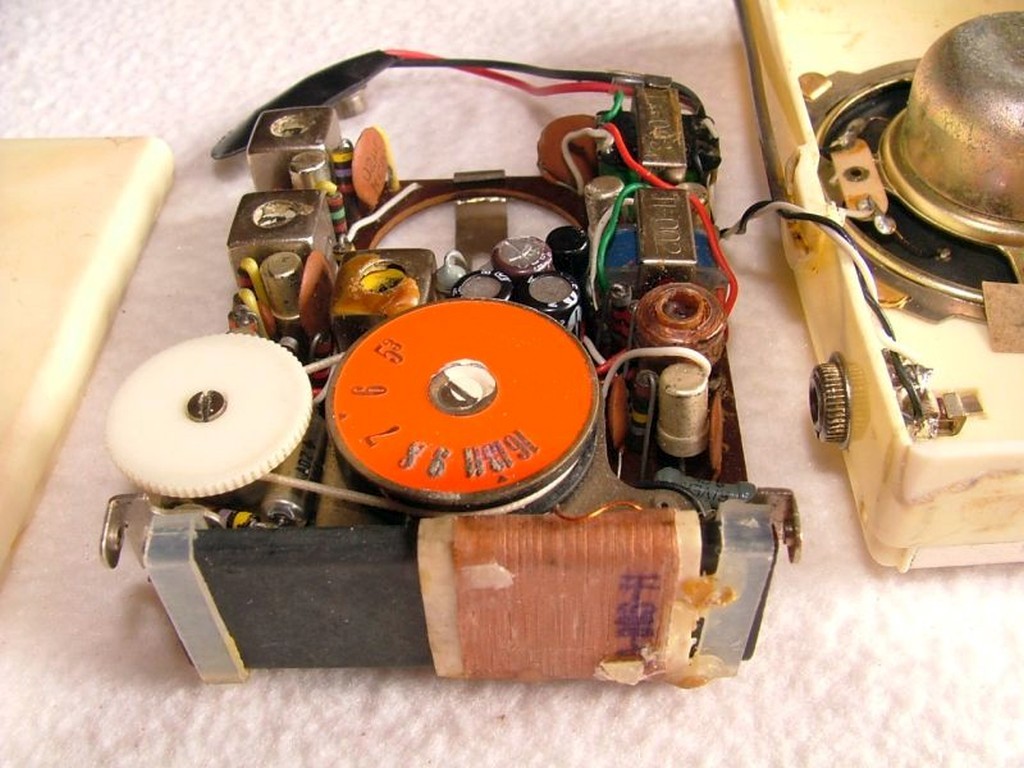
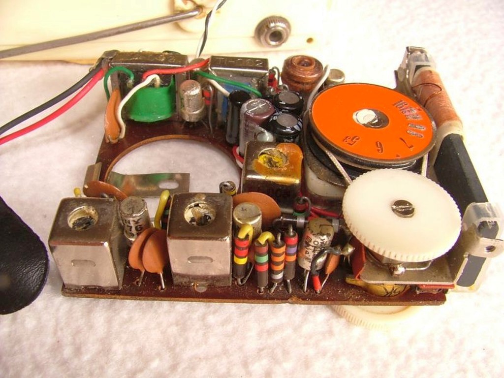
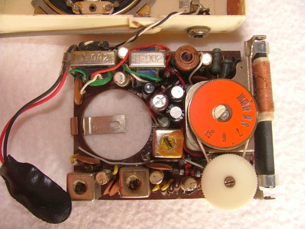
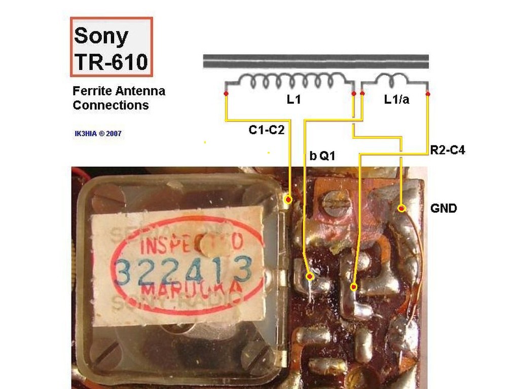
Using an ohmmeter, I identified the ends
of the windings of L1 and L1/a: the one with the lowest resistance was
definitely L1/a. At this point I soldered the four wires to the radio
circuit board by referencing diagram.
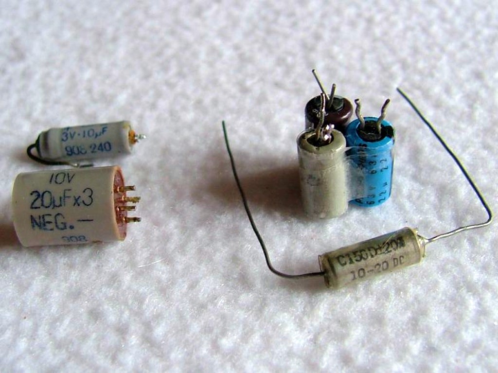
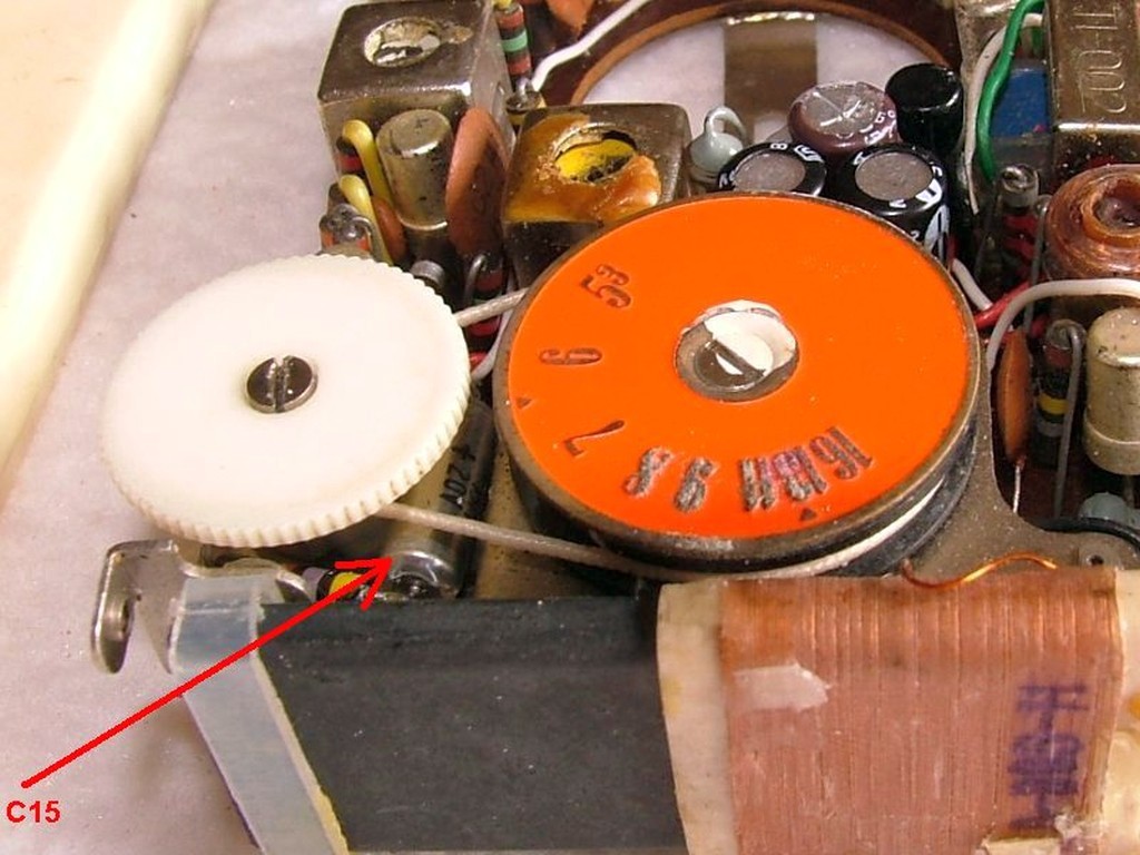
To replace
C15 with a
new 10MF 20V Work component, it was sufficient to remove the volume and
the tuning knobs to free the printed circuit and solder the new
capacitor in place of the old one with R13 on the negative pole. |
|||||||
 |
 |
 |
 |
||||
 |
 |
 |
 |
||||
 |
 |
 |
 |
||||
|
|
|||||||
|
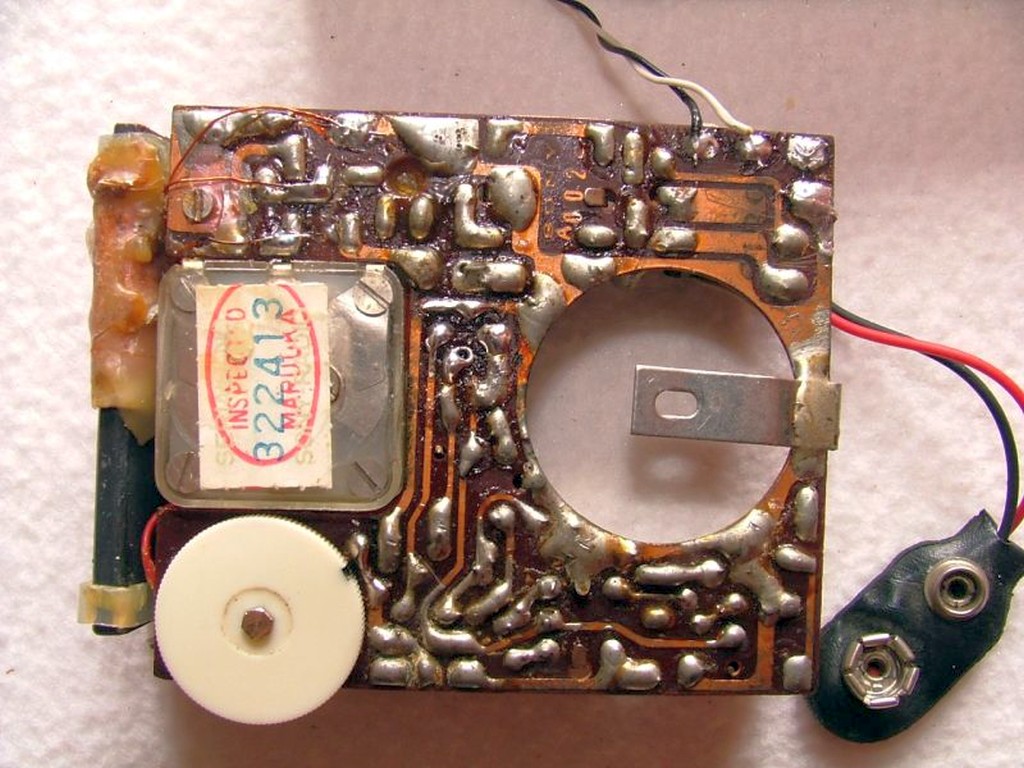
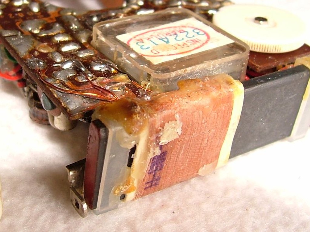
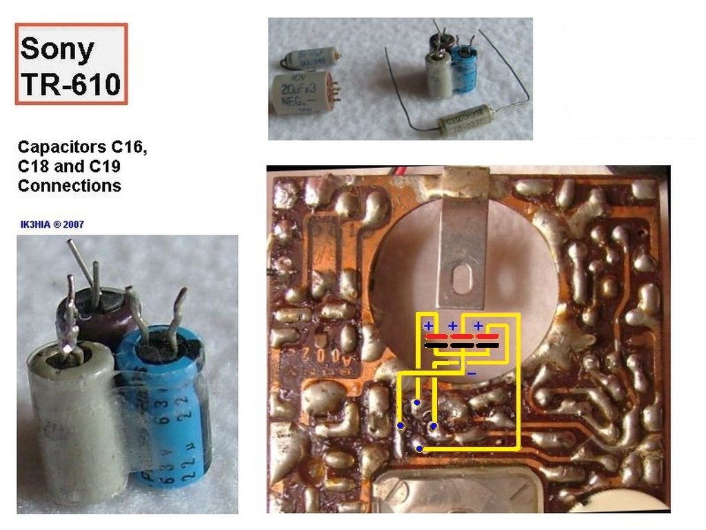
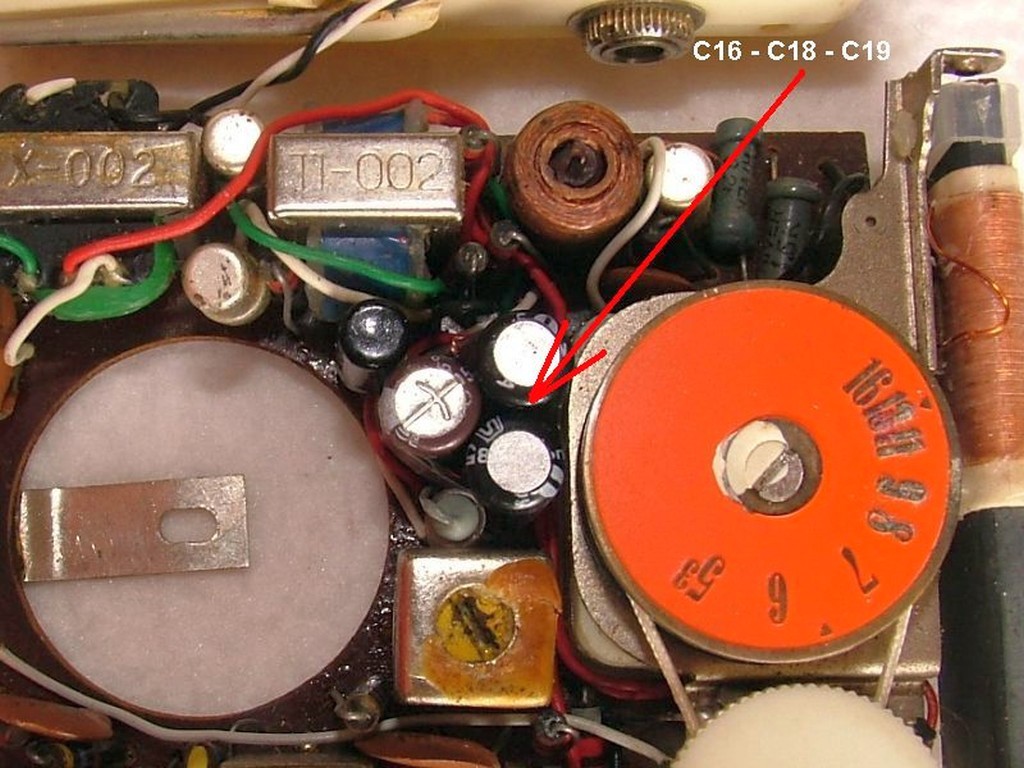
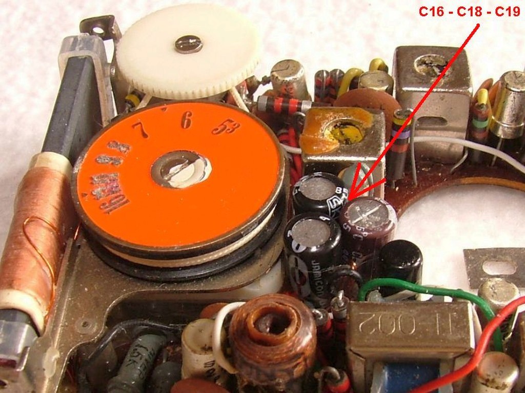
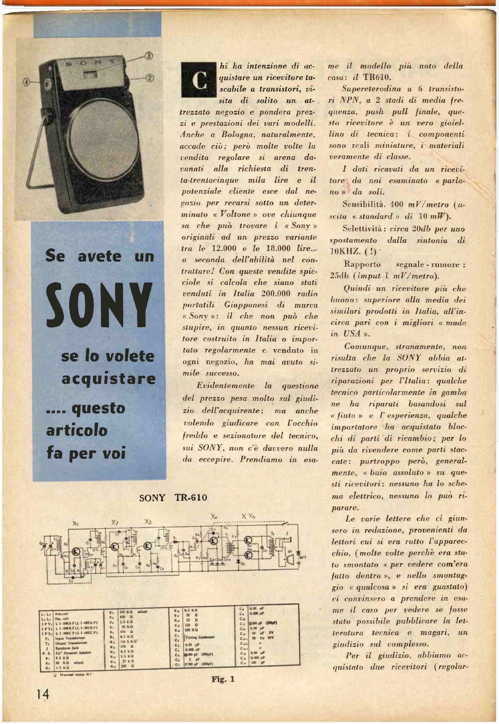
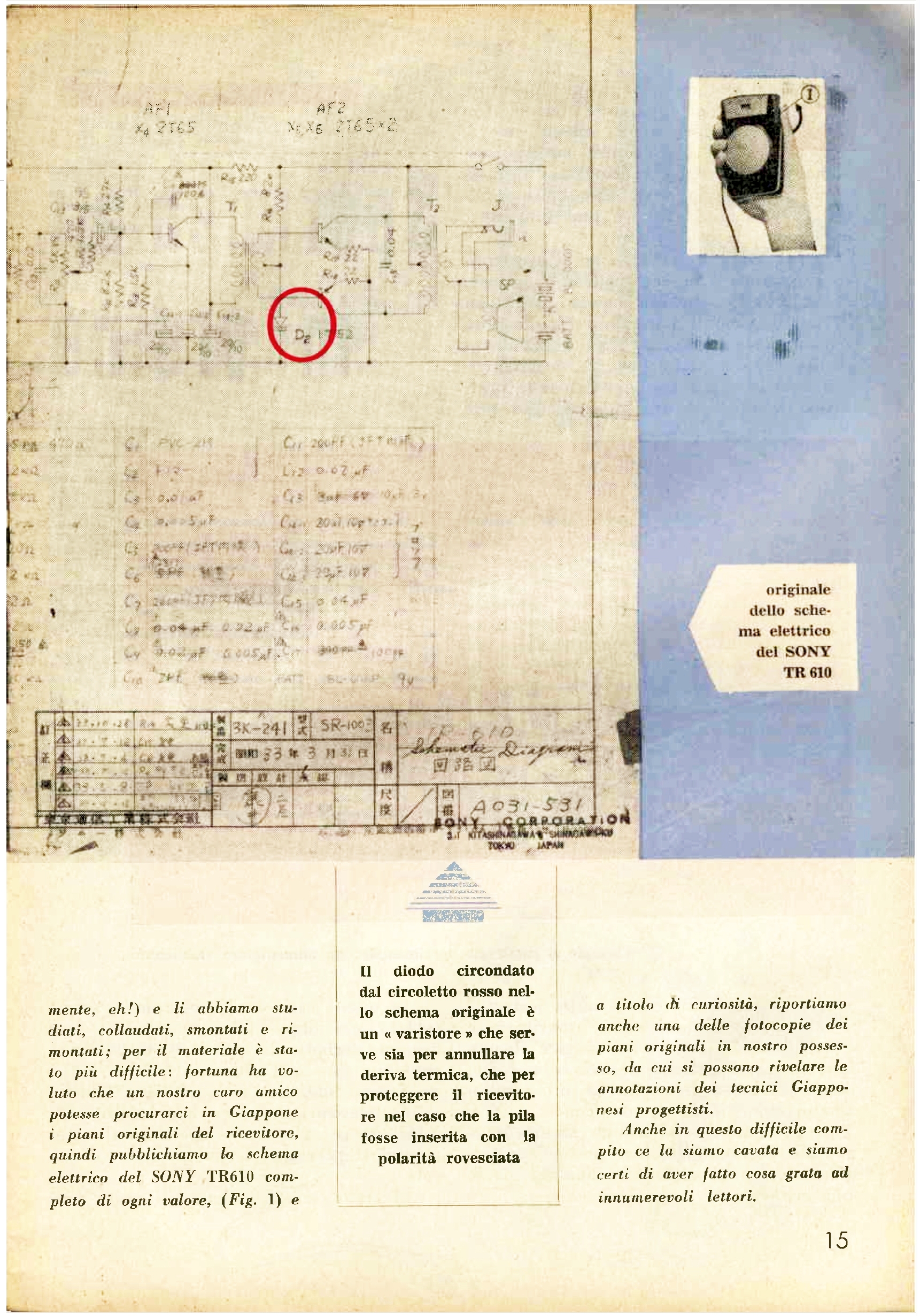
Con tanta pazienza e usando un affilato taglierino sono riuscito a liberare i corti monconi dei fili spezzati dallo strato di cera che copriva la bobina, così ho potuto togliere la vernice che copriva i monconi e saldarli a degli spezzoni di filo da 0,2 mm (AWG 32) tolti da un ex trasformatore. Ho coperto le saldature con del nastro adesivo trasparente e ho bloccato il tutto sul corpo della bobina con della cera fusa da una candela. Con l'utilizzo di un Ohmetro ho individuato i capi degli avvolgimenti di L1 e L1/a: quello con la resistenza più bassa era sicuramente L1/a. A questo punto ho saldato i quattro filetti al circuito stampato della radio facendo riferimento a questo schema. Dopo la sistemazione dell'antenna in ferrite, sintonizzando la radio dall'altoparlante uscivano dei deboli fischi, ma questo risultato mi ha incoraggiato a proseguire. Il passo successivo è stata la taratura dei nuclei delle bobine di Media Frequenza utilizzando un generatore di RF sintonizzato a 455 kHz e un piccolo cacciavite di plastica, ma dopo tale operazione non ho ottenuto alcun miglioramento. L'azione che si è rivelata vincente è stata invece la sostituzione di tutti i condensatori elettrolitici presenti nella radio. La TR-610 utilizza quattro condensatori elettrolitici: uno è da 10 MF (C15) ed è collegato tra il potenziometro del volume e la base del primo transistor di BF, gli altri sono: C16 da 10 MF, C18 e C19 da 20 MF che sono inseriti tutti assieme nello stesso involucro. Per rimpiazzare C15 con un nuovo componente da 10MF 20V lavoro è stato sufficiente togliere le due manopole di volume e sintonia per liberare il circuito stampato e saldare il condensatore nuovo al posto del vecchio con R13 sul polo negativo. Per la sostituzione degli altri tre elettrolitici era impossibile rintracciare un componente simile, così ho trovato nel mio magico cassetto tre piccoli condensatori da 22 MF e 20 V lavoro e li ho uniti con un po' di nastro adesivo. I tre nuovi componenti sono entrati perfettamente nello spazio occupato dal vecchio triplo condensatore. Ho saldato assieme i tre reofori negativi collegandoli ad un'unico filo che ho saldato a massa, i tre reofori positivi li ho saldati saldati nelle rispettive piazzole del circuito stampato. Dopo questa operazione, accendendo la radio e sintonizzandola a 936 kHz, dall'altoparlante è uscita a tutto volume l'emittente di RAI-1 che trasmette nella mia zona. Il lavoro di riparazione ha avuto successo e l'esemplare di TR-610 è entrato con onore a far parte della mia collezione. © IK3HIA, 2007 |
|||||||
|
|
|||||||
 |
 |
 |
 |
||||
 |
 |
 |
 |
||||
 |
 |
 |
 |
||||
|
Return to top of
page
|
|||||||
|
|
Return to: IK3HIA home page |
|
Return to: Transistor Radio |
|
Go to: Transistor diagrams |