Barlow Wadley XCR-30 Mk2
South Africa - 1973
Italiano

   Click on the images to enlarge  
     
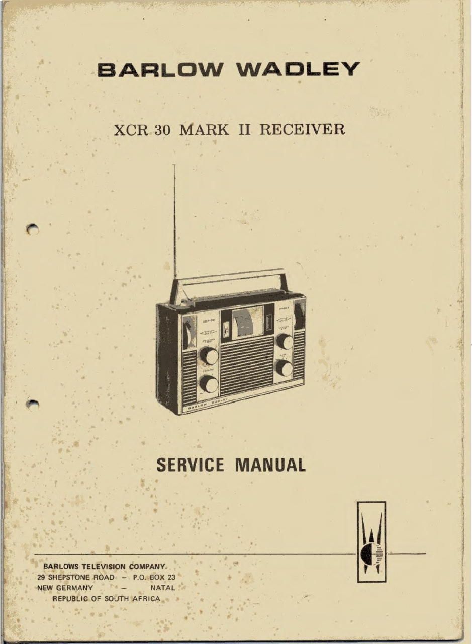
Barlow Wadley mod. XCR-30 Mk2 - BARLOWS MNFG. Co. Ltd. South Africa ZA (Republic of South Africa) - 1973.

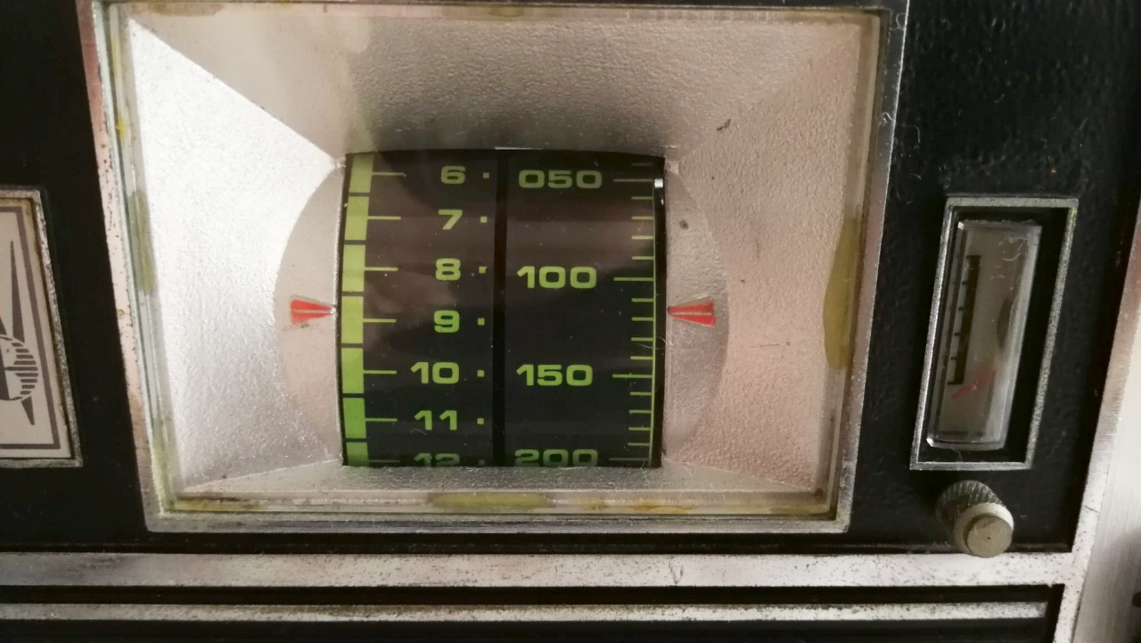
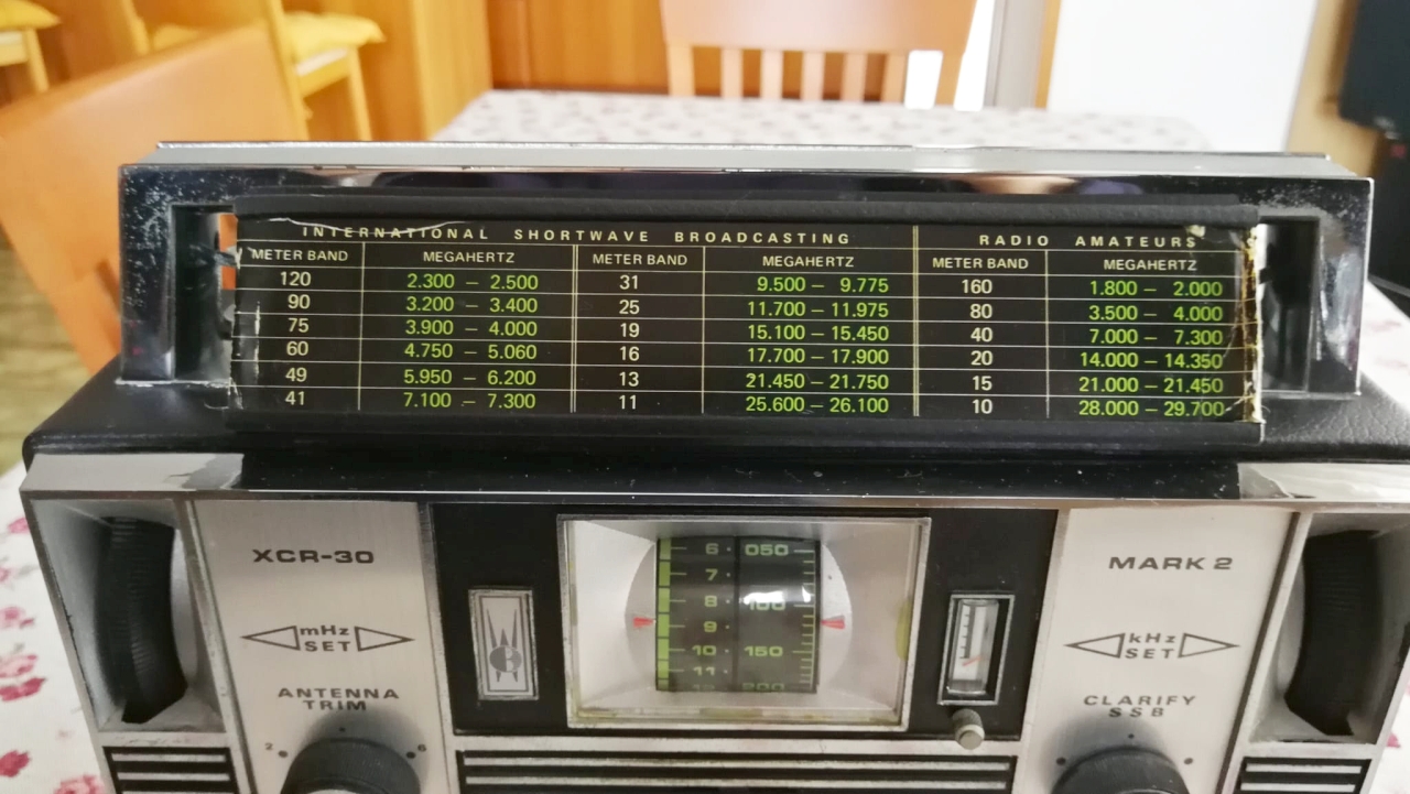
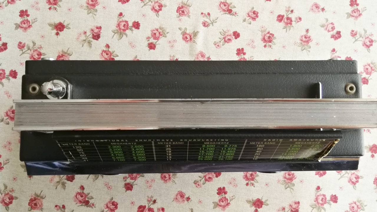
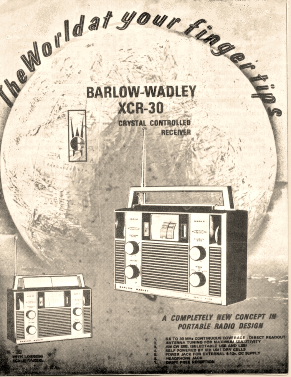
The XCR-30 is a portable, high-sensitivity, continuous coverage receiver in the HF range. It is designed to provide excellent sensitivity and precise frequency tuning across the entire frequency spectrum from 500 kHz to 30 MHz, with 
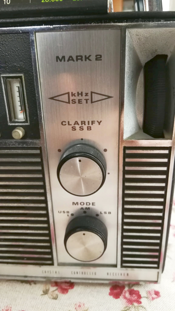
high stability for both AM (amplitude modulation), CW (telegraphy), and SSB (single sideband) transmissions.

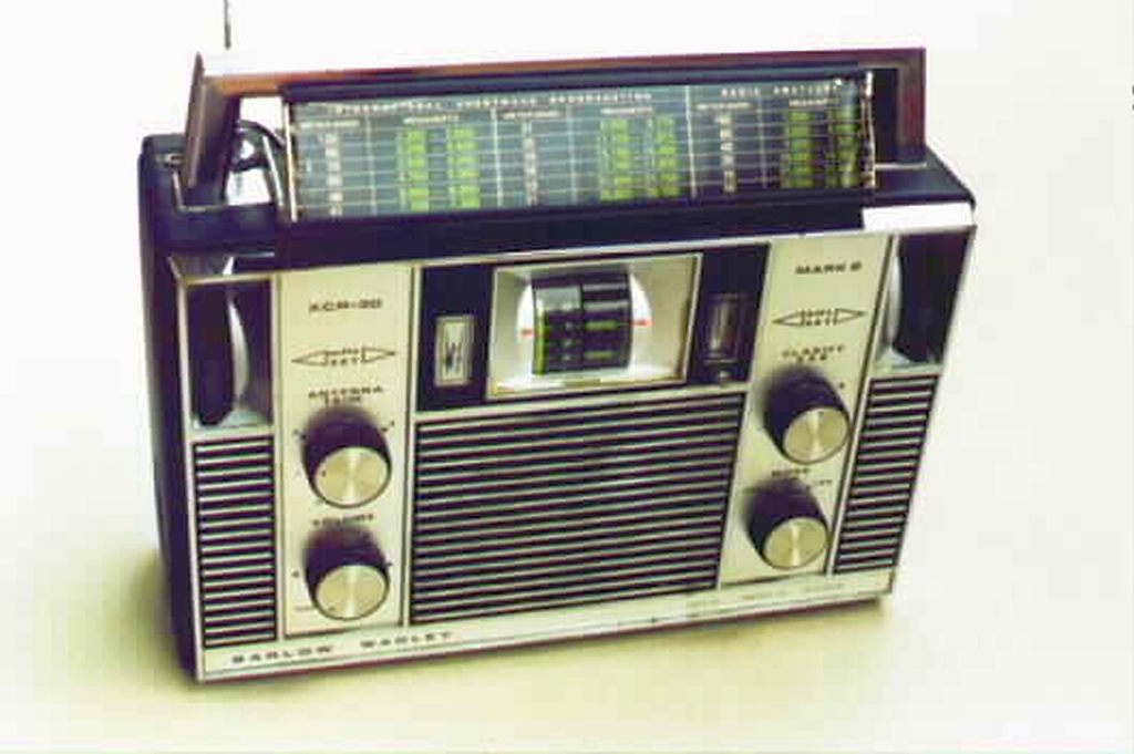
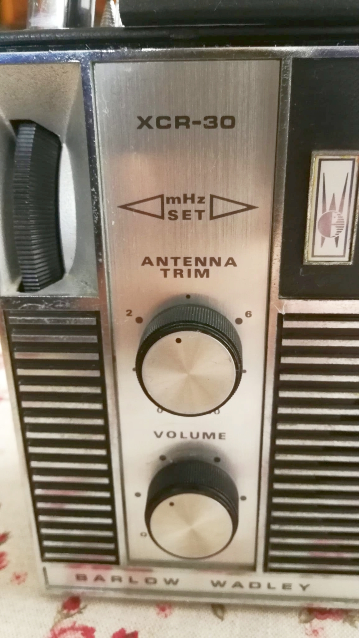
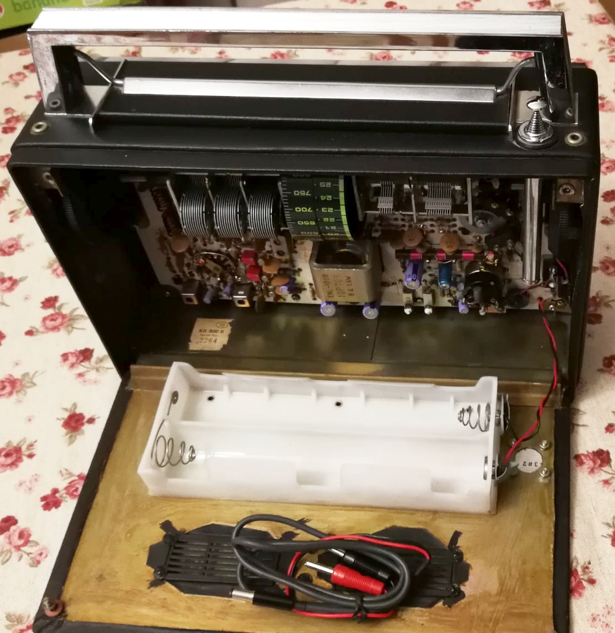
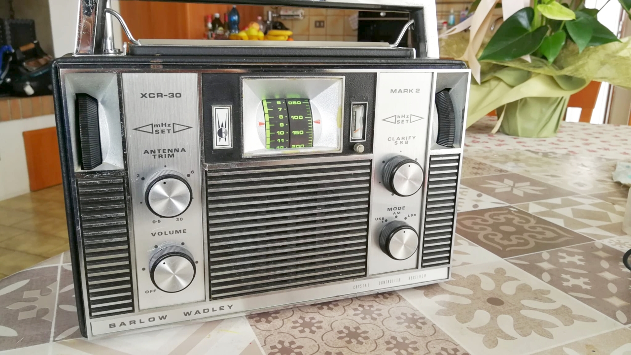
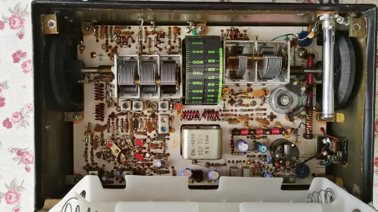
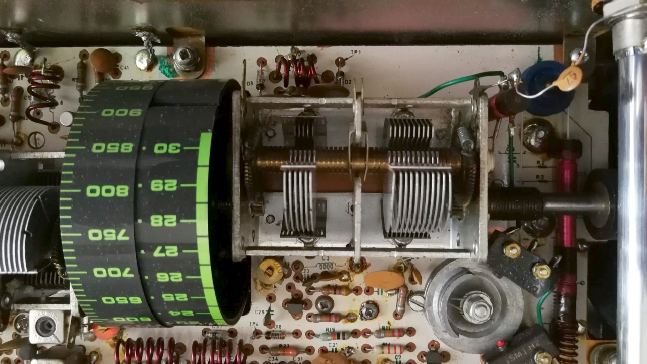
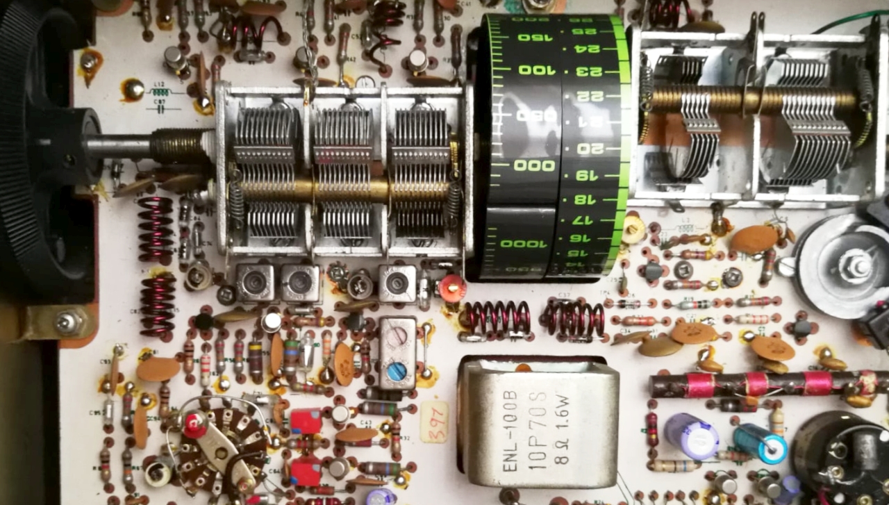
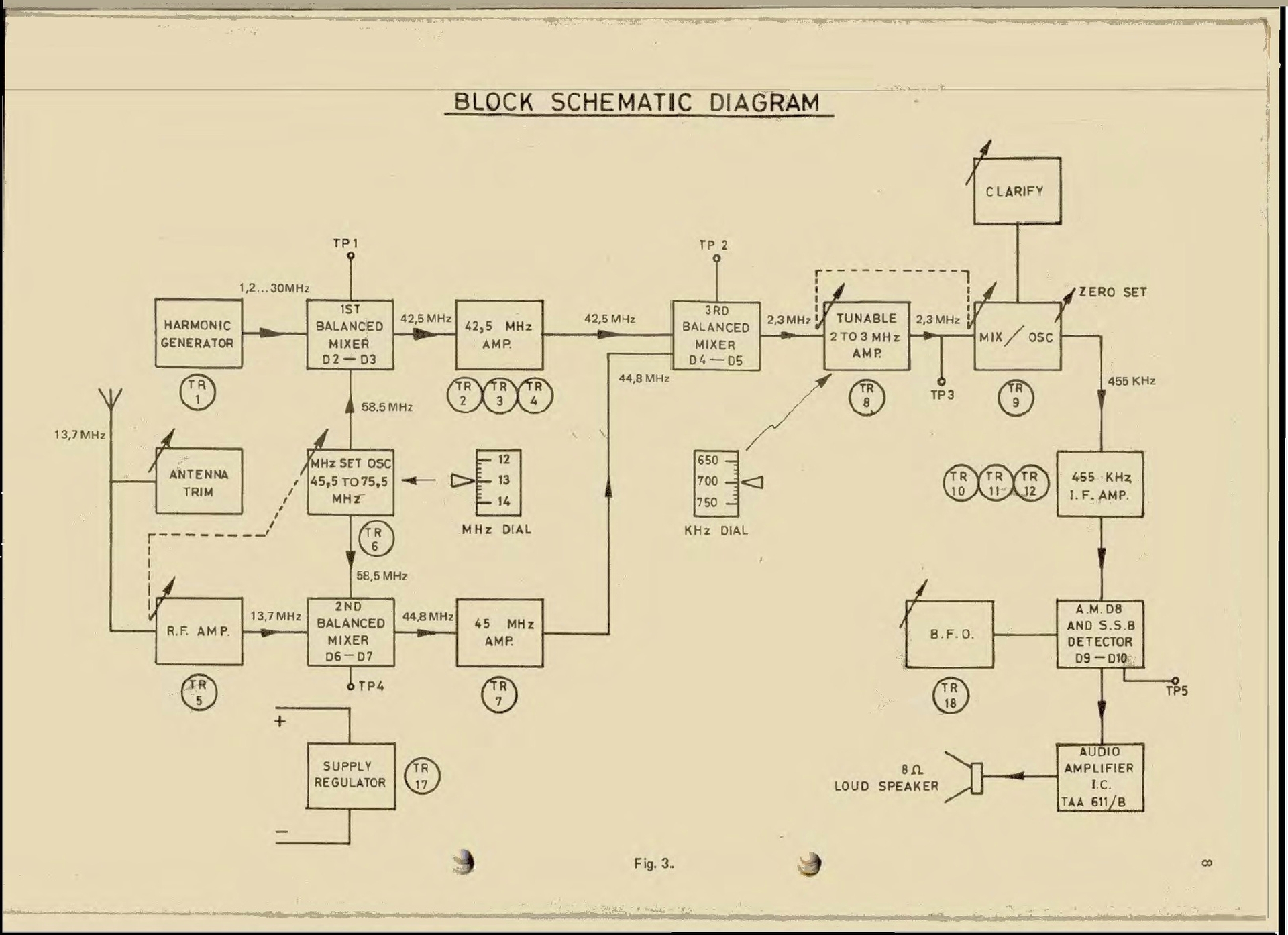
The receiver has a spartan, rather homely appearance, but inside it contains a triple-conversion superheterodyne circuit and is stabilized by a quartz oscillator to eliminate tuning drift over long periods of operation and to provide a stable single sideband tone. The receiver uses the synthesized heterodyne oscillator known as the "Wadley Loop System."

Trevor Lloyd Wadley (1920-1981) was a South African electronics engineer, known for inventing and patenting the Wadley Loop circuit in 1948, which was used in radio receivers to facilitate tuning without switching coils or crystals. The first radio receiver to use the Wadley Loop was the British Racal RA-17 in 1957, while the Barlow XCR-30 was built in South Africa in the late 1960s. The Wadley loop circuit was also used in other receivers such as the Drake SSR1 and the more popular and famous Yaesu FRG7.

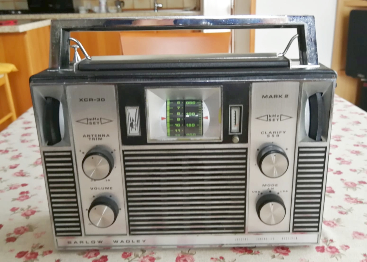
The XCR-30 was produced in South Africa starting in 1969, and the MK2 model was released in 1973. 
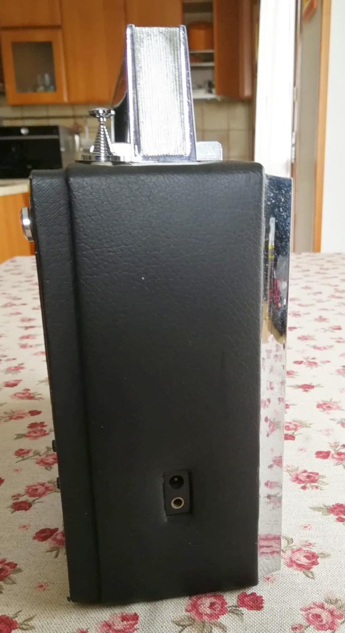
The Barlow Wadley was a portable radio designed to allow South African settlers, living on plantations and in the most remote locations of the country, to listen to radio broadcasts not only from South Africa's major cities but also from around the world.

The receiver was cutting-edge for its time, but due to the apartheid regime in force at the time in the Republic of South Africa, the XCR-30 did not have a large diffusion abroad, South African trade and products were boycotted and it was also difficult for South African factories to obtain the components necessary for production. 
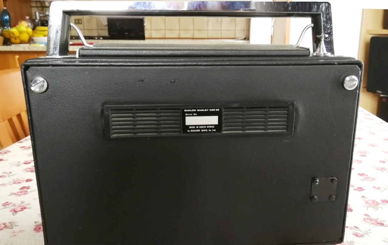
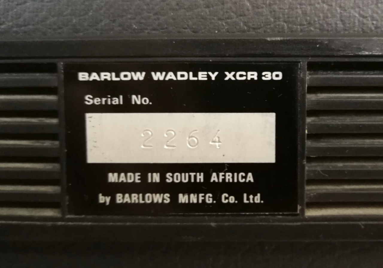
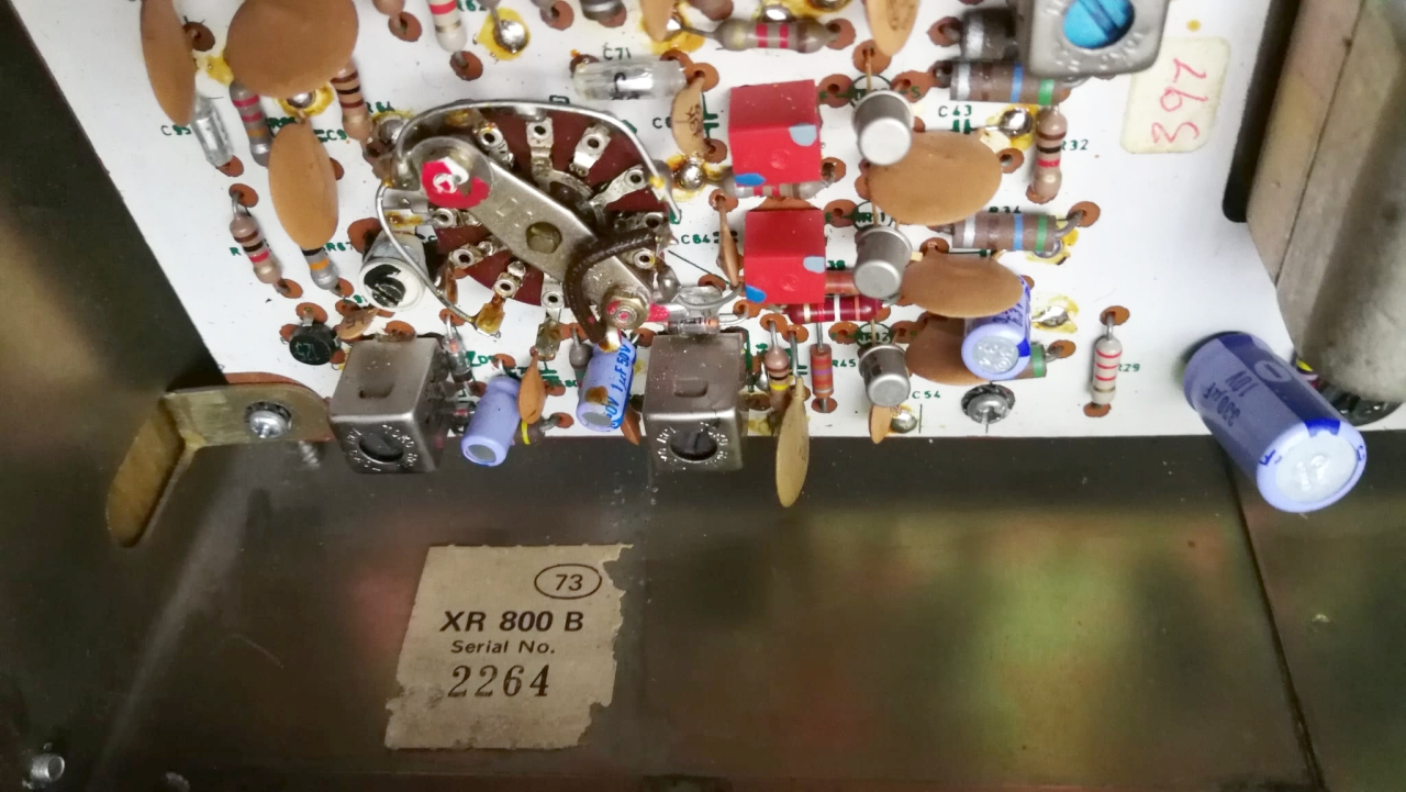
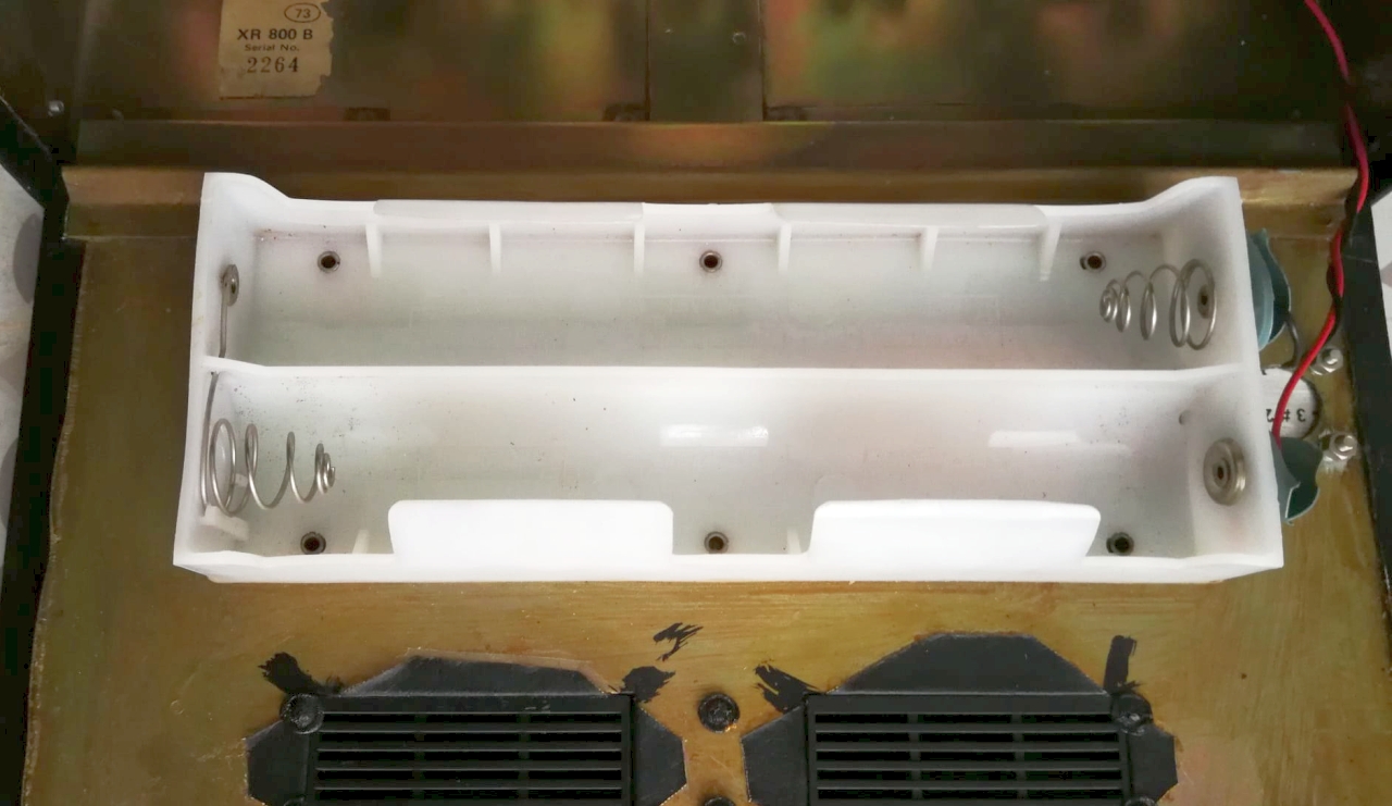
Barlow, however, managed to produce approximately twenty thousand units of this receiver. The Mk2 model shown in the photos was built in 1973 and has serial number 2264.

(continued below)
       
The 1973 XCR-30 Mk2 uses 15 transistors, nine of which are BF255 silicon transistors used in the high-frequency circuits, and a BC108 and BC262 silicon transistors in the low-frequency preamplifier. The audio output stage is a single-ended transistor consisting of an AC117 and an AC175 germanium transistor. An AC188 serves as a voltage regulator, and an AC122 serves as a diode to protect the radio from reverse power supply polarity. Both transistors are germanium.

The radio's front panel has two indicator drums on the sides, operated by coaxial knobs: one from 0 to 30 MHz indicates the MHz portion of the frequency to be received, while the other has notches from 0 to 1000 for selecting the kHz. The frequency scale is accurate to within 5 kHz on all frequencies.

The radio has an 31.496in long whip antenna located to the left of the carrying handle. With the whip, you can easily hear very weak signals, such as those from amateur radio on SSB and CW. Alternatively, near the whip is a socket for connecting an external wire antenna. Opposite the handle is the ground socket.

There are seven controls on the radio's front panel. Two tuning knobs, to the right of which is the S-meter with a reset knob. On the left side of the front panel is the antenna trimmer, and below it is the volume control with the power switch. On the right side is the BFO (Clarify) control, and below it is the USB-AM-LSB switch.

When operating in SSB, the BFO (Clarify) knob can shift the main frequency calibration by +/- 1.5 kHz (3 kHz total). The XCR-30 has a selectivity of 6 kHz on AM and 3 kHz on SSB/CW. Audio output is 0.5 watts into a 3.1-inch speaker with an 8-ohm impedance. A headphone jack is located on the left side of the cabinet.

(continued below)
The XCR30's cabinet is made of metal, with faux leather-covered brass panels and other metal alloy parts, making it quite heavy. On the top, under the carrying handle, is a movable slide containing cards. The external color card displays the frequencies of commercial and amateur radio stations. Below are blank cards for recording listening data (logs).

It is powered by six 1.5 V DC UM-1 batteries for a total of 9 volts, or by using the external power socket above the headphone jack. The radio can be powered by a DC voltage ranging from 6 to 12 volts. Dimensions are 11.5 x 7.5 x 3.9 inches, and it weighs 8 lb 13 oz without batteries.

I purchased this radio at the Mantua (Italy) electronics fair in 1973 and I used it for a long time as the station receiver. After 52 years, the XCR30 still works perfectly and receive weak radio signals inside home with its small whip antenna. The only repair I made was years ago when I had to replace the AC117 power protection transistor (I used an AC135) because it burned out when for mistake I connected the + and - pins of the power cable the wrong way round.

IK3HIA © 2004 - 2025
       
Return to top of page

Go up - torna su. Return to: ik3hia home page Go up - torna su. Return to Old Ham radio page