 |
Oscilloscopio mod. TVN
- Scuola Radio Elettra Torino, Italy ~ 1955. |
|
|
|
Oscilloscopio mod. TVN
- Scuola Radio Elettra Torino, Italy ~ 1955. |
|
 Italiano
 |
English
 |
||
|
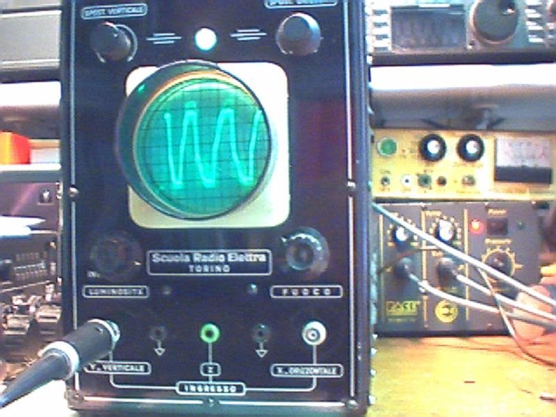
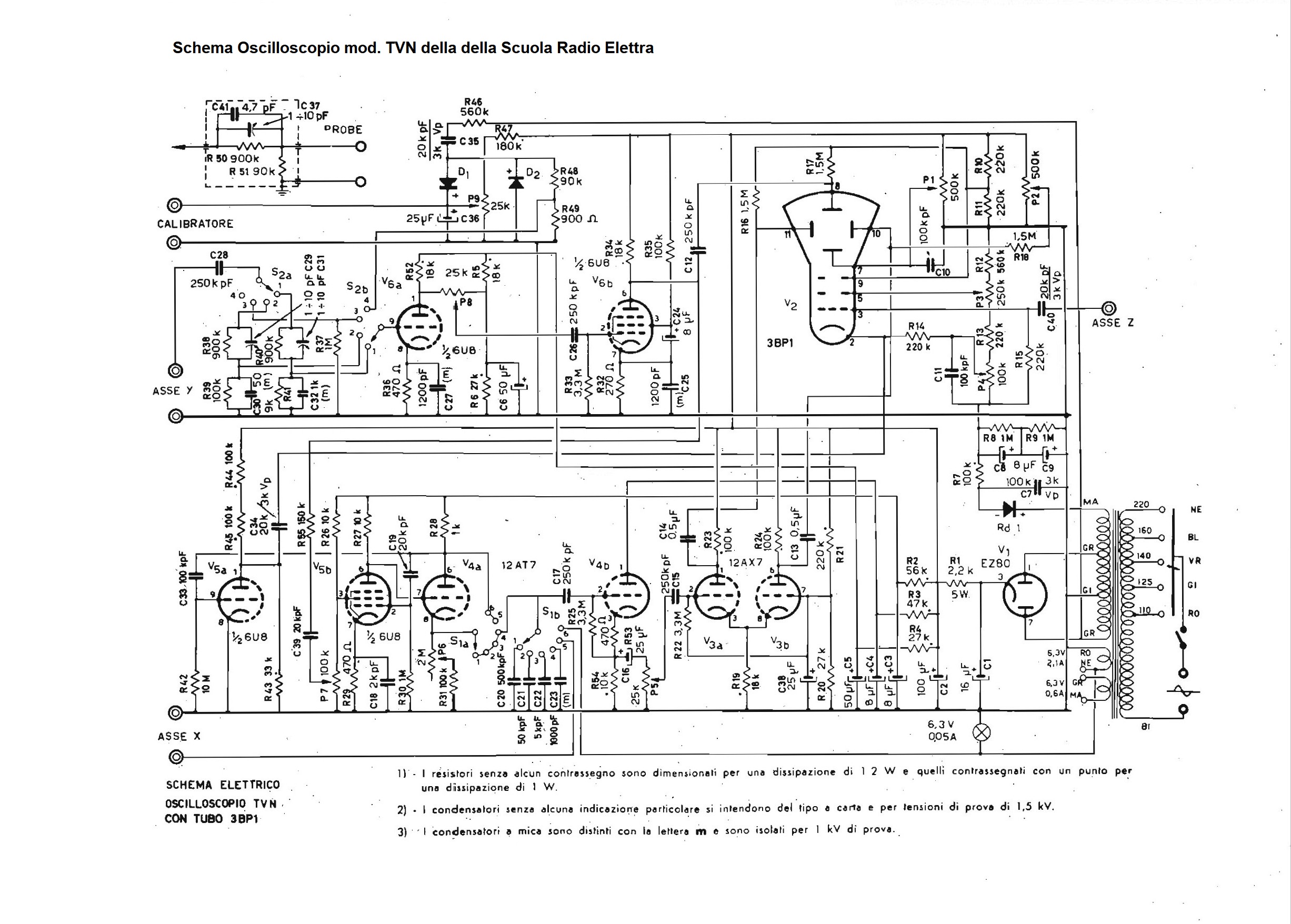
L'oscilloscopio TVN
faceva parte delle apparecchiature da assemblare inviate dalla Scuola
Radio Elettra assieme alle dispense delle lezioni ai partecipanti ai
corsi per corrispondenza di Radio e TV negli negli anni '50 e 60. Per l'epoca e per l'uso didattico a cui era destinato, l'oscilloscopio era abbastanza avanzato perché con i comandi posti sul pannello frontale e su quello superiore si potevano regolare la posizione orizzontale e verticale, il sincronismo e la luminosità e la messa a fuoco della traccia. Sul pannello frontale, attorno allo schermo del tubo catodico c'erano i comandi per lo Spostamento Verticale e lo Spostamento Orizzontale della traccia, la Luminosità e il Fuoco e le boccole per gli ingressi Y(Verticale), X (Orizzontale) e dell'asse Z per la modulazione del fascio di elettroni che generava la traccia luminosa. All'ingresso dell'asse Verticale Y potevano essere applicate tensioni da pochi millivolt fino a 300 V con apposita sonda. I comandi sul pannello superiore erano: Ampiezza Verticale, Ampiezza Orizzontale, Sincronismo, Scansione, Sensibilità Verticale e la Base dei Tempi del generatore di sincronismo che variava da 8 Hz a 50 kHz. Lo strumento era inoltre dotato di un calibratore interno per la misura del valore picco picco dell'ampiezza verticale (asse Y). Lo strumento utilizzava un tubo catodico a fosfori verdi da 3" tipo 3BP1 alimentato con un particolare raddrizzatore al selenio che forniva i 900 V necessari per applicare l'alta tensione alle placchette. Per le varie funzioni, il circuito del TVN impiegava 6 valvole miniatura a nove piedini: 2 x 6U8, 12AT7, 12AX7 e una rettificatrice biplacca EZ80 per il raddrizzamento della tensione anodica. L'alimentazione avveniva tramite rete con cambio tensione da 110 a 220 Vac. Le dimensioni dell'oscilloscopio erano: Dimensioni (LxAxP) 18 x 27 x 30 cm, e il peso era di 7,5 Kg. © IK3HIA, 2005. |
|||
 |
 |
 |
 |
 |
 |
 |
 |
|
The TVN oscilloscope was part of the equipments in kit sent by the
Elettra Radio School together with the lecture notes to the participants
in the Radio and TV correspondence courses in the 1950s and 60s. For the time and for the educational use for which it was intended, the oscilloscope was quite advanced because with the controls located on the front and top panels, it was possible to adjust the horizontal and vertical position, the synchronism, the brightness and the track focusing. On the front panel, surrounding the CRT screen were controls for Trace Vertical and Horizontal Shift, Brightness and Focus, and jacks for the Y (Vertical), X (Horizontal) and Axis inputs Z for the modulation of the electron beam that generated the luminous trace. Voltages from a few millivolts up to 300 V could be applied to the input of the vertical Y axis with a special probe. The controls on the top panel include: Vertical Amplitude, Horizontal Amplitude, Sync, Scan, Vertical Sensitivity and the Sync Generator Time Base which ranged from 8Hz to 50kHz. The instrument was also equipped with an internal calibrator for measuring the peak-to-peak value of the vertical amplitude (Y axis). The instrument used a 3" type 3BP1 green phosphor cathode tube fed with a special selenium rectifier that supplied the 900 V needed to apply the high voltage to the plates. For the various functions, the TVN circuit employed 6 miniature nine-pin valves: 2 x 6U8, 12AT7, 12AX7 and an EZ80 biplate rectifier for rectifying the anode voltage. The power supply was via mains with voltage change from 110 to 220 Vac. The oscilloscope dimensions were: (WxHxD) 7.1 x 10.6 x 11.8 inch, and the weight was 16lb 8.5oz. © IK3HIA, 2005. |
|||
|
Torna a
inizio pagina
|
|||
| Return to IK3HIA home page | Return to Instruments page |