 |
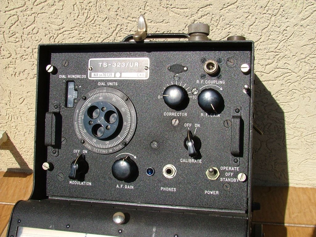
Frequency Meter TS-323/UR Hoffman Radio Corp. U.S.A. - 1942. |
|
|
|
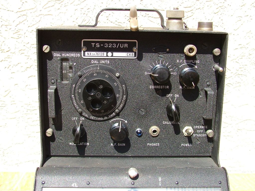
Frequency Meter TS-323/UR Hoffman Radio Corp. U.S.A. - 1942. |
|
|
|
English
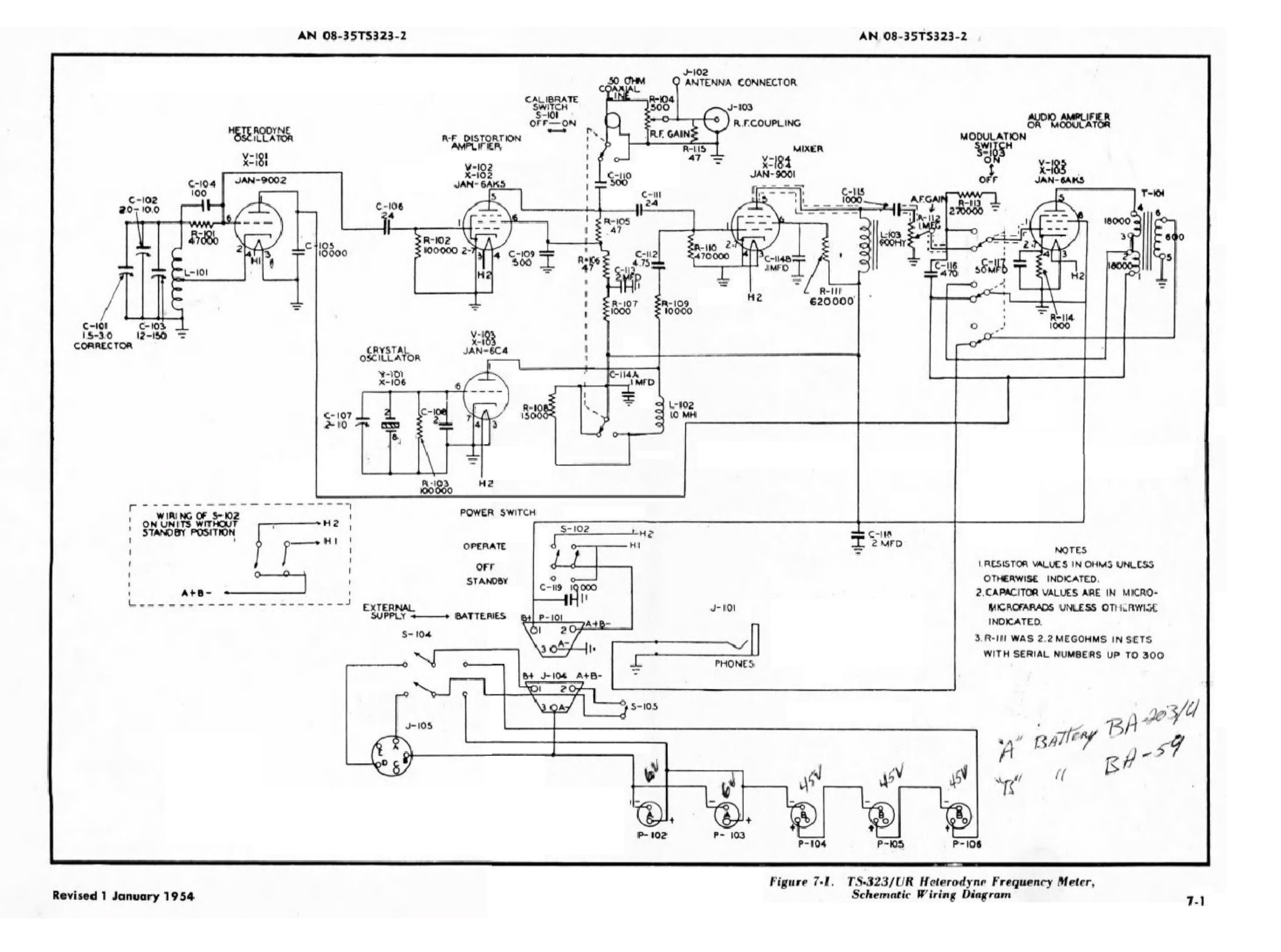
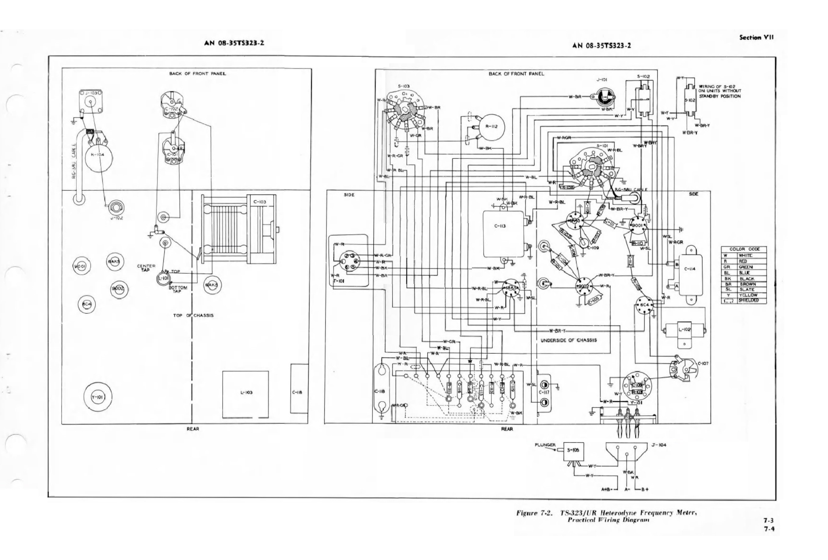
Schematic diagrams |
||||
|
|||||
|
Click sulle immagini per ingrandire
|
|||||
 |
 |
 |
 |
||
 |
 |
 |
 |
||
 |
 |
 |
 |
||
|
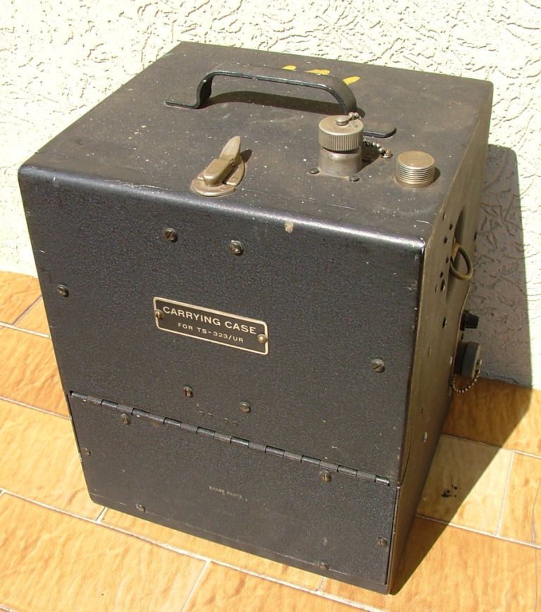
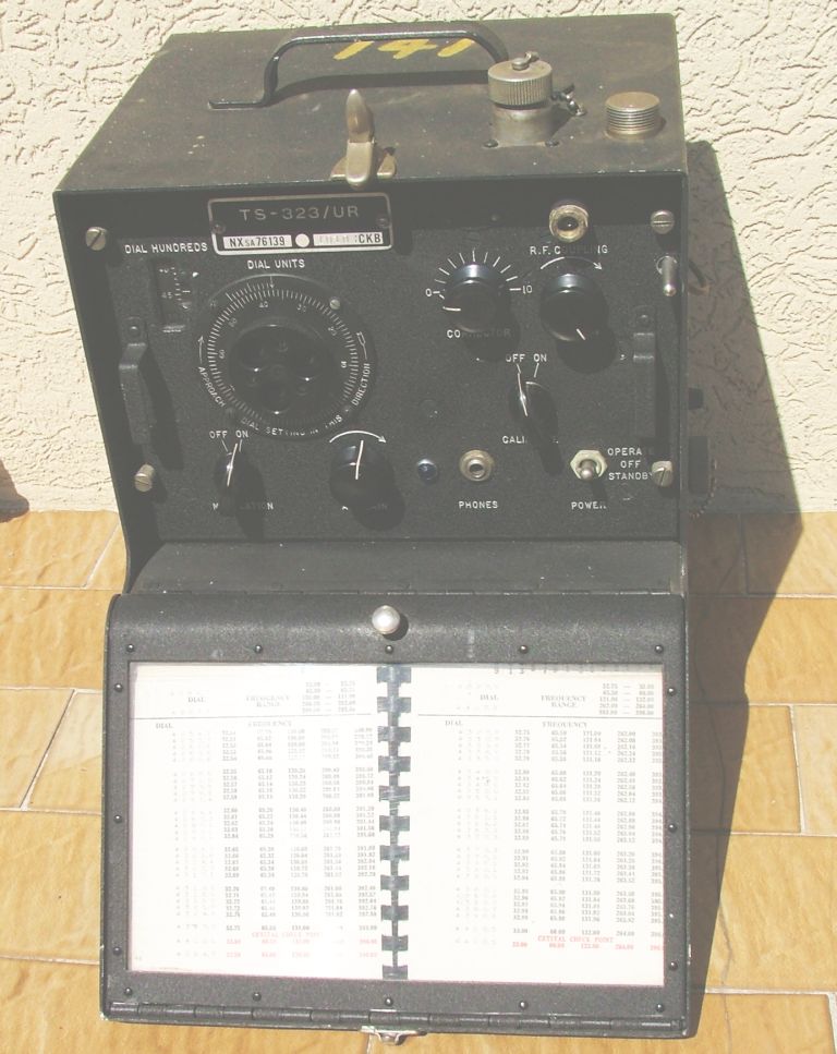
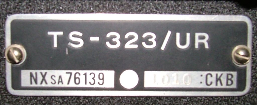
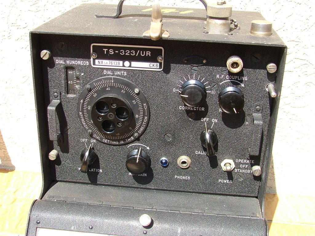
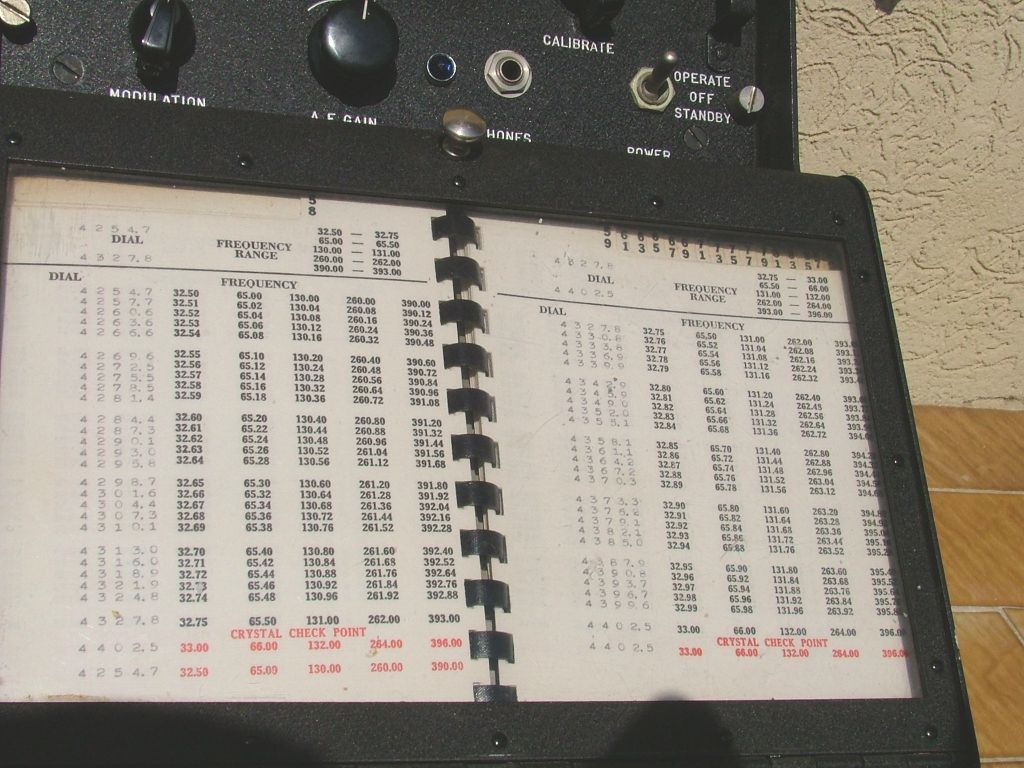
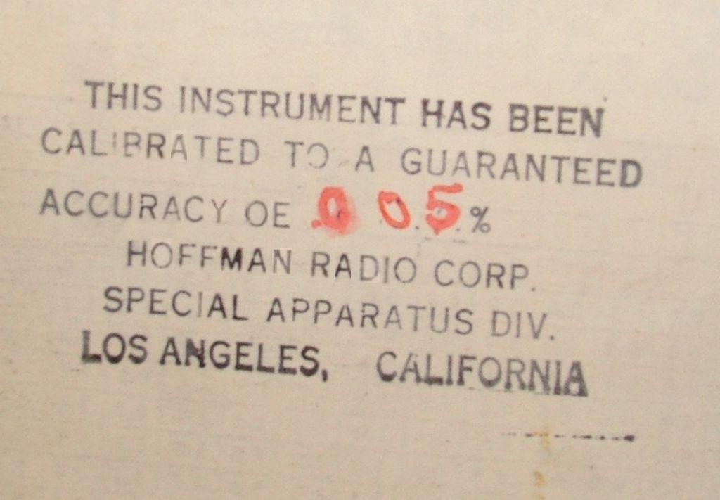
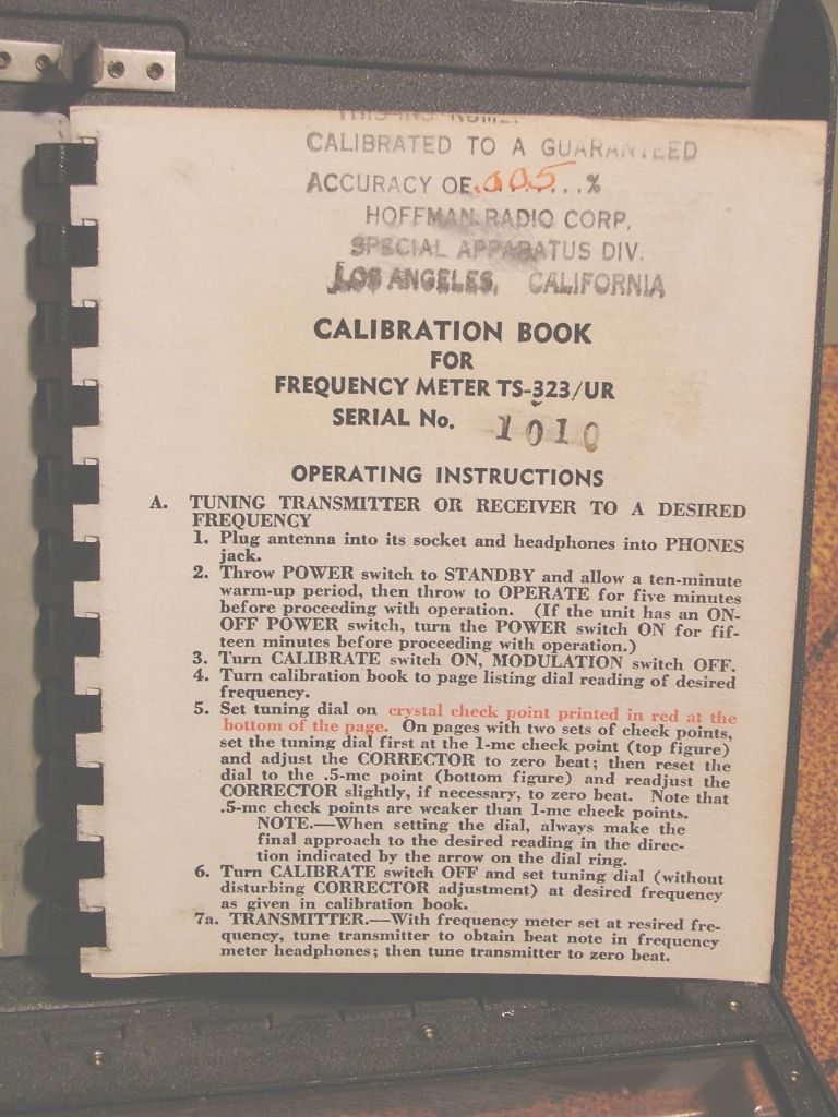
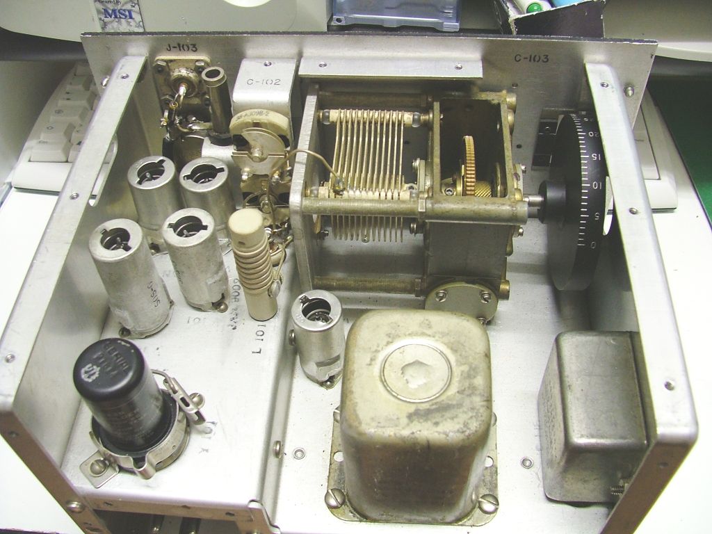
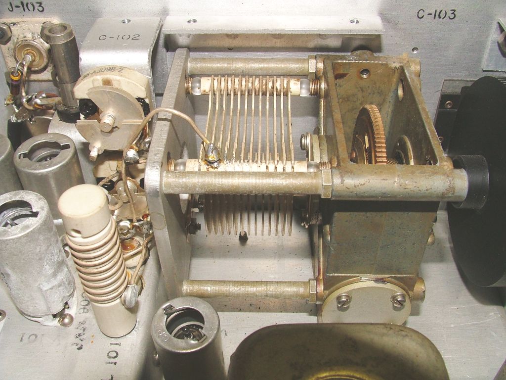
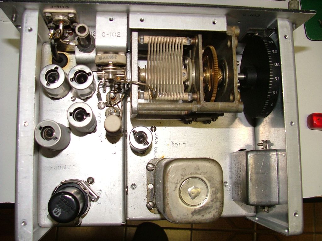
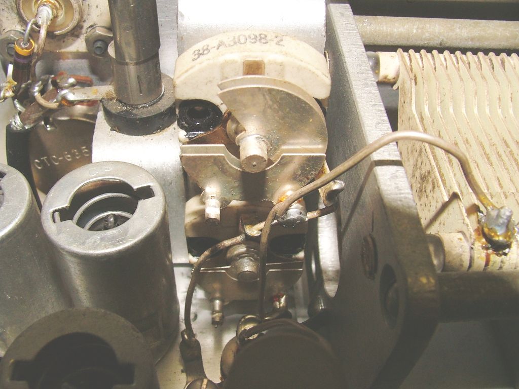
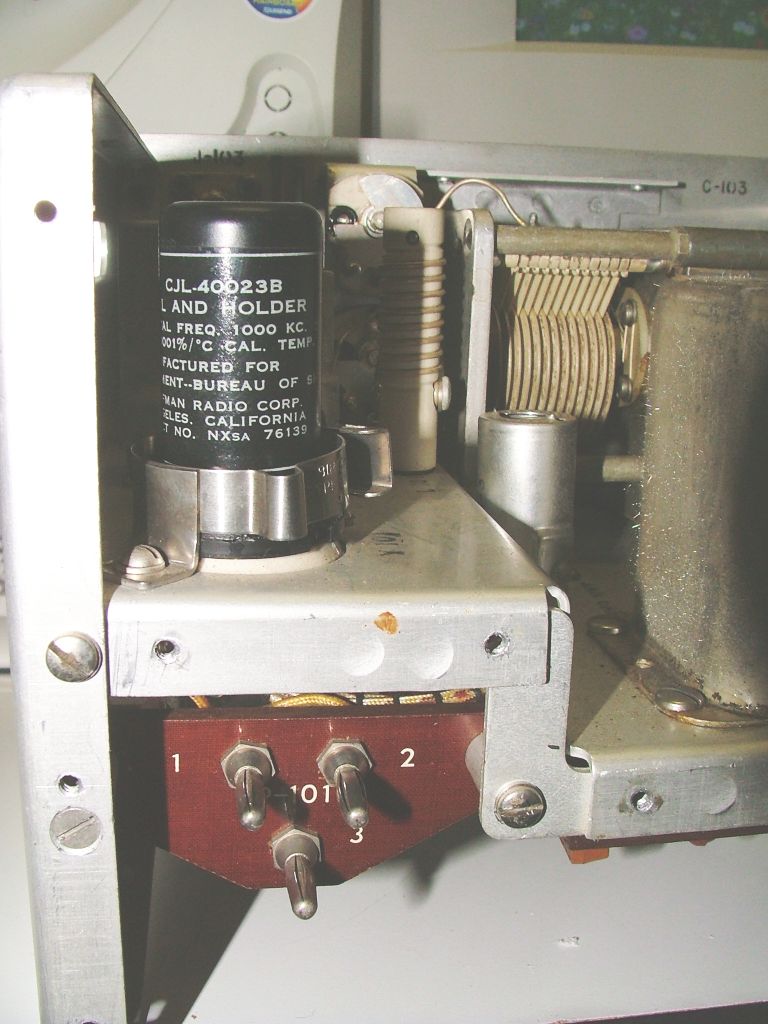
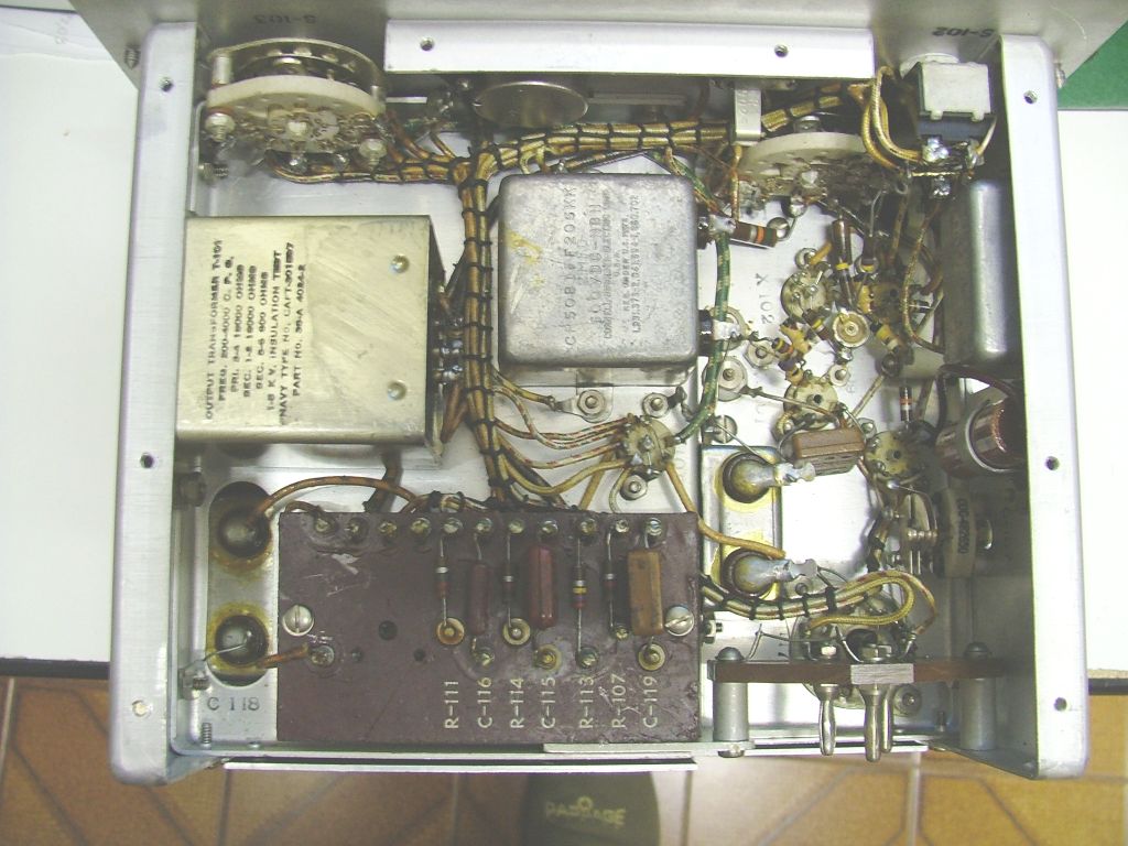
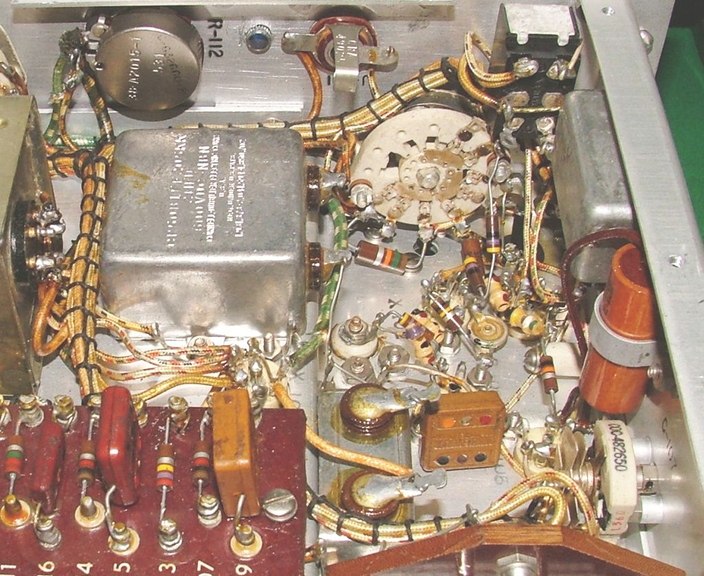
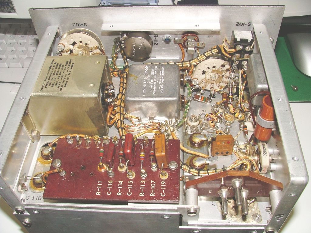
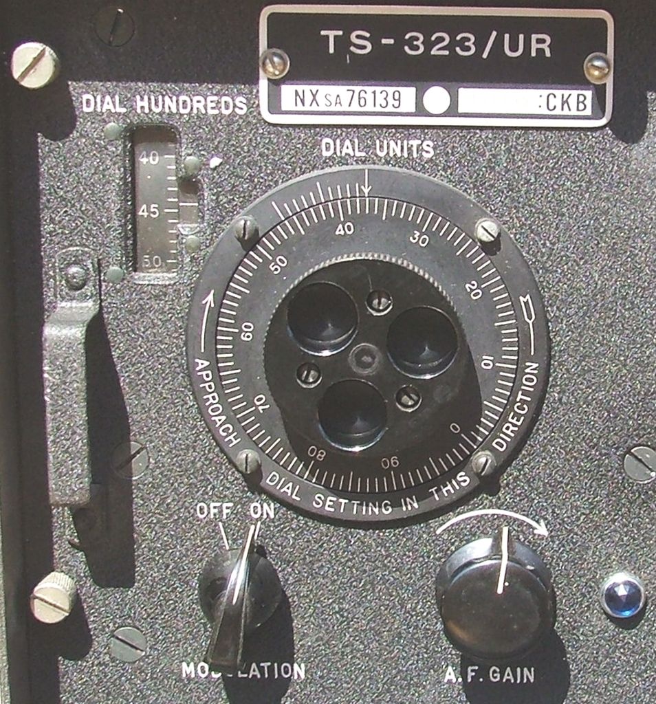
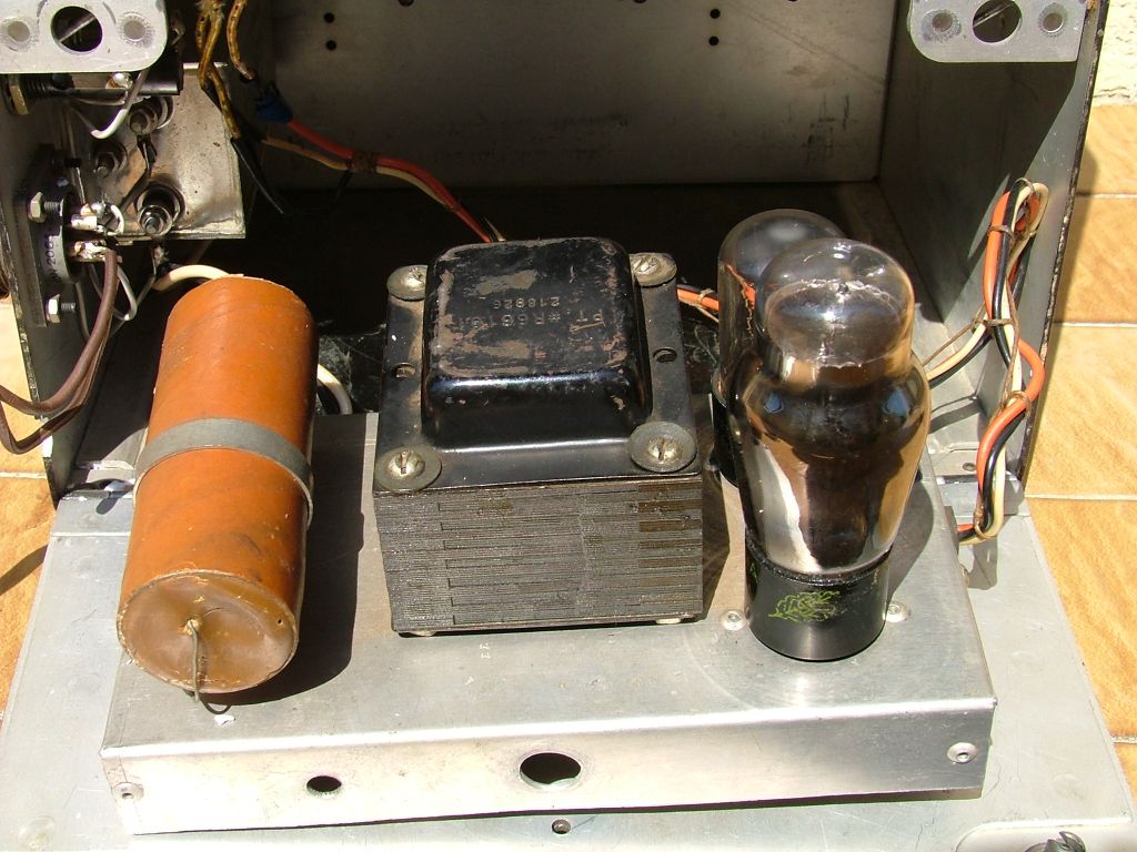
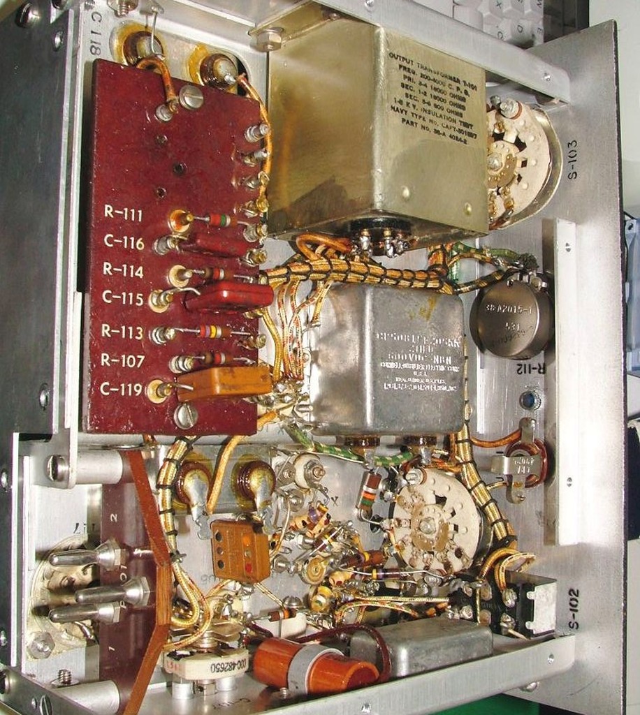
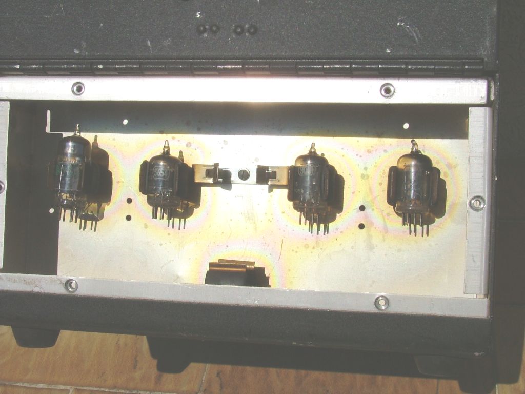
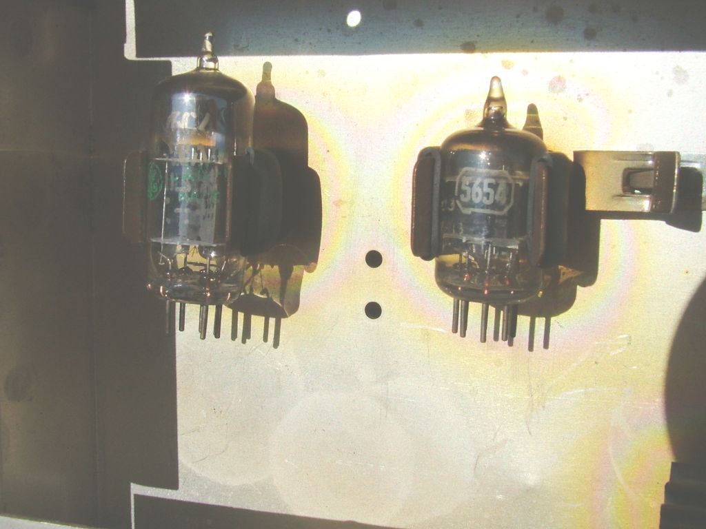
The circuit of the TS-232/UR used 5 thermionic tubes: 9002, 6C4, 9001, and #2 6AK5. A telescopic antenna could be inserted into the connector located on the top of the cabinet. Headphones were used to listen to the beat between the unknown frequency and the local oscillator. Power could be supplied by batteries: 2 x BA-203/U in parallel supplied the 6 V for the filaments and ) and 3 x BA-59 in series supplied the 140 V for the anodic. Alternatively, the appropriate stabilized mains power supply could be inserted inside the battery compartment. In the lid that covered the front panel there was the booklet with the values to be read on the vernier and through which it was possible to know the beat frequency. Under the front door there was another compartment closed by a plate with 6 screws, inside which the valves and the spare crystal were placed. This example (serial number 1010) was built by Hoffman Radio Corporation, Los Angeles, California U.S.A. in 1942. © IK3HIA, 2005 |
|||||
 |
 |
 |
 |
||
 |
 |
 |
 |
||
 |
 |
 |
 |
||
|
Torna a
inizio pagina
|
|||||
|
|
Return to Instruments
page
|