
|
|
MULTIVOLTAGE POWER SUPPLY |
|
|
|
 |
Descrizione
|
|
 |
|||
|
Click sulle immagini per
ingrandire
|
|||
 |
 |
 |
|
|
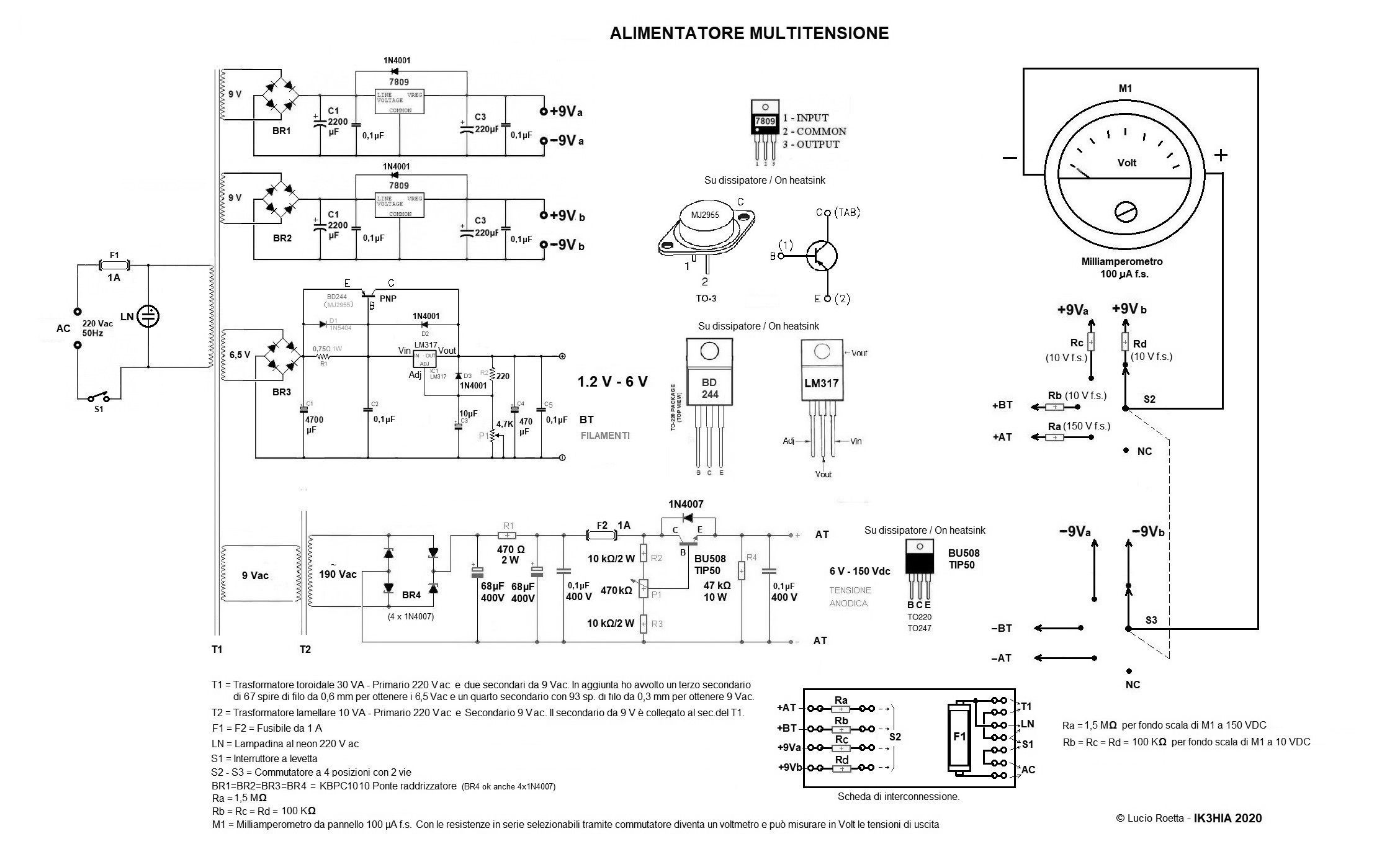
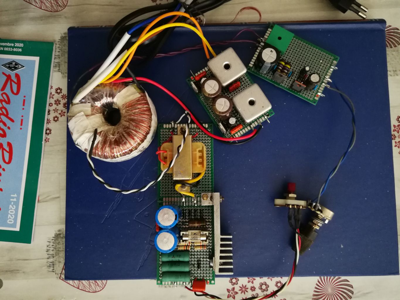
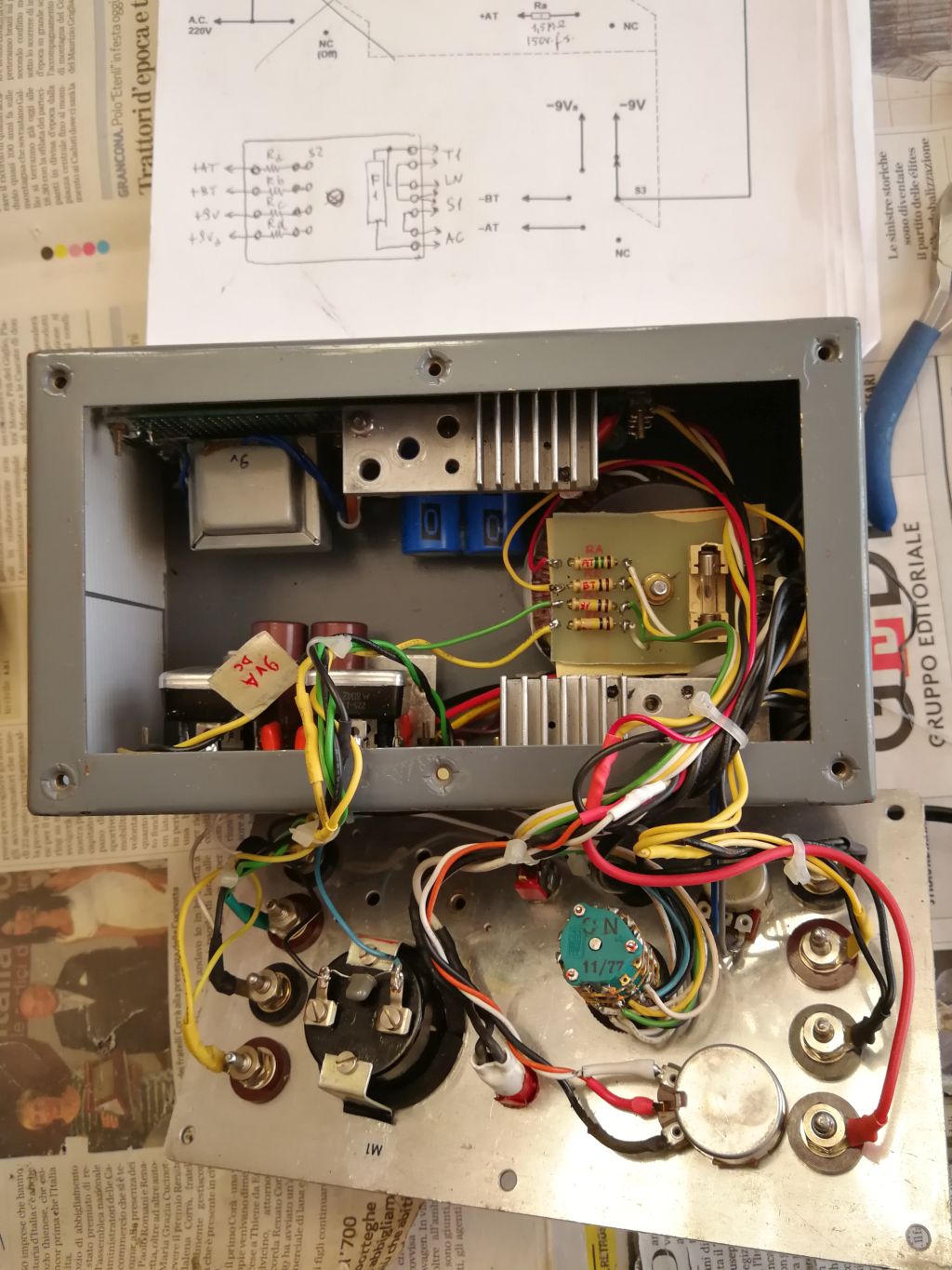
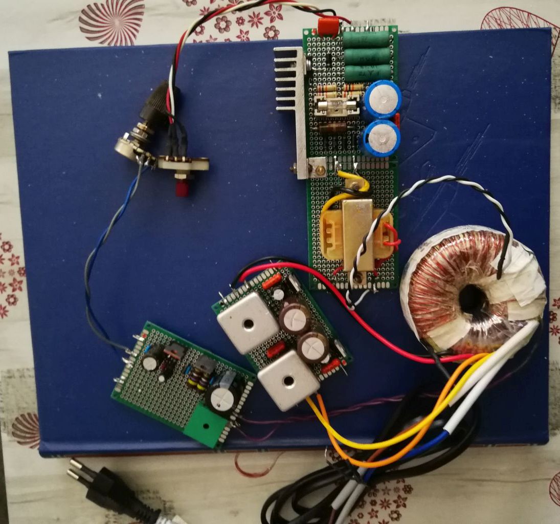
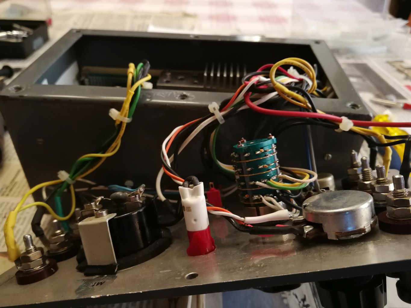
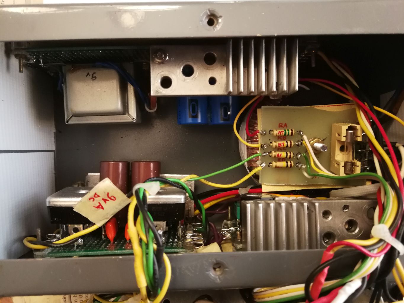
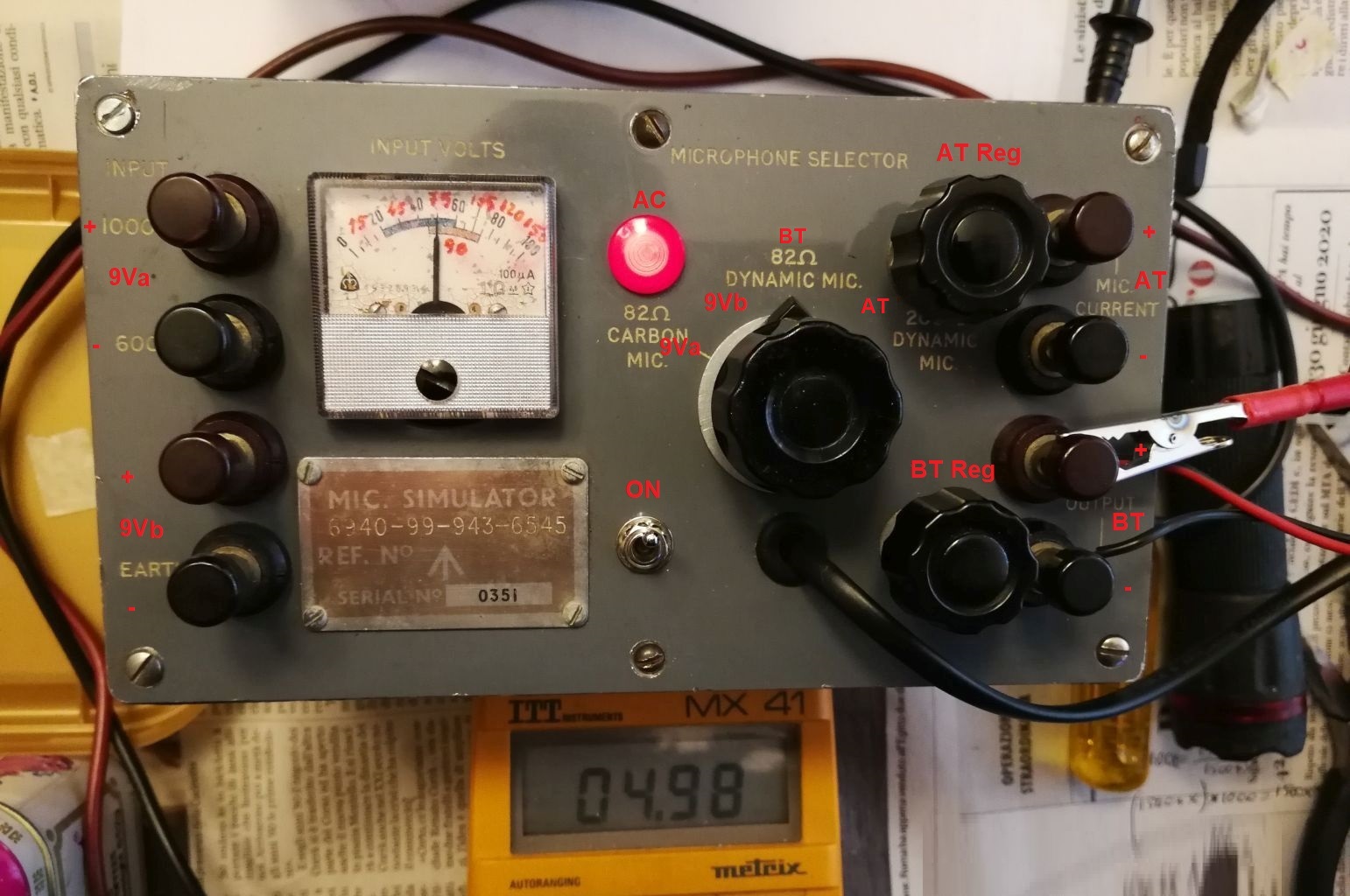
I created this project in order to be able to power the old transistor radios and the ancient portable tube radios that I like to restore and put back into operation. Many transistor devices require 9 volts, the older ones require 9 + 9 Volts or 12 V, others 6 Volts and the most recent 3 Volts. The first portable transistor receiver, the Regency TR1, of which I have put back into operation the specimen visible in this link, requires as much as 22.5 Volts to work. All these voltages can be obtained directly or by placing the terminals of this power supply in series. For portable valve radios, which use the series of miniature tubes with 1.4 Volt filament and the 45 or 90 Volt anode, the two voltages can be taken from the four terminals on the right and are adjustable with the two potentiometers. Looking at the wiring diagram, you can see that the T1 transformer has four secondaries and it is difficult to find a similar one on the market, but it is possible to make it with a DIY job. You must therefore buy a toroidal transformer of at least 30 VA with two 9V secondaries and then modify it by adding two more secondaries, one of 6 V and one of 9 V (see photo 2). To make the 6 V secondary, you must prepare a 7.5 meter long piece of 0.6 mm enameled copper wire, block one end with adhesive tape and wrap 70 turns side by side. This is done by patiently inserting the other end seventy times into the central hole of the toroid. The wire is quite rigid and tends to twist during the task, but patience is the virtue of experimenters and the saints help to overcome the most difficult moments. Once the turns are wound, they will need to be blocked with insulating tape, then you can proceed with the winding of the 9 V secondary. Even if it is necessary to wind more turns, in this case the work will be made easier by the thinner diameter of the enameled wire (0.3 mm) so, after having cut a piece of about 10 meters, you can wind it on a piece of cardboard of the appropriate size that can pass freely through the central hole of the toroid. The winding will begin by blocking one end of the wire with the usual adhesive tape, then the spool will enter and exit easily from the hole like a spool, making it easier to wind the 95 turns. Insulated wires with different colors will be soldered to the ends of the newly wound windings in order to make them easy to identify, then everything will be blocked with several turns of insulating tape. At this point, you can verify the success of the undertaking by carefully powering the toroid with the 220 Vac mains and measuring the alternating voltages on the various secondaries with the tester. If the voltages are lower, due for example to the difference in thickness of the toroid, it will be enough to add a few turns with the same copper wire. The second transformer (T2) used in the circuit is a normal lamellar transformer (but a toroidal will also do) of at least 15 VA, with the primary of 220 Vac and the secondary of 9 Vac. The 9 V secondary of this transformer must be connected to the 9 V secondary just wound on the T1. In this way, the T2 will act as a voltage booster and once connected and powered at the ends of its primary there will be approximately 190-200 Vac. The sturdy metal box I used is an old Signal Corps U.S.A. surplus, which I found among the countless scraps that clutter my garage and which I chose because it was already equipped with the eight terminals needed for the outputs and the round hole for the analog instrument, but nothing prevents you from using a modern container and new red and black terminals. The board you see in the center right of photo 5 is made with a small piece of glass fibre and includes the mains fuse holder, the pins cennected to the power switch, the neon bulb and the mains cable, and the resistors Ra, Rb, Rc, Rd which are selected via a 2-way, 4-position switch to be able to read the various output voltages on the Voltmeter (a 100 micro Ampere milliammeter). At the end of the assembly, with my digital voltmeter I measured the following voltages on the eight terminals: 9 V, 9 V; 1.2 - 6V; 6 - 150 Volts. The two variable voltages drop a little under load, but remain within the useful values for any need. It is possible to connect the output voltages from two or more power supply terminals in series because the four circuits are independent, and the voltage regulators and power transistors are all installed on heat sinks separated from ground by mica insulation. © IK3HIA 2021. |
|||
 |
 |
 |
|
|
Return to top of page
|
|||
|
Ho realizzato questo progetto allo scopo di poter alimentare le vecchie radio a transistor e le antiche radio portatili a valvole che mi piace restaurare e rimettere in funzione. Molti apparecchi a transistor necessitano di 9 volt, i più vecchi richiedono 9 + 9 Volt oppure 12 V, altri 6 Volt e i più recenti 3 Volt. Il primo ricevitore portatile a transistor, la Regency TR1, della quale ho rimesso in funzione l'esemplare visibile in questo link, necessita addirittura di 22,5 Volt per poter funzionare. Tutte queste tensioni sono reperibili direttamente o ponendo in serie i morsetti di questo alimentatore. Per le radio portatili a valvole, le quali utilizzano la serie di tubi miniatura con filamento a 1,4 Volt e l'anodica a 45 o a 90 Volt, le due tensioni sono prelevabili dai quattro morsetti di destra e sono regolabili con i due potenziometri. Osservando lo schema elettrico si nota che il trasformatore T1 ha quattro secondari e difficilmente se ne può trovare uno simile in commercio, ma è possibile realizzarlo con un lavoro fai da te. Si deve pertanto acquistare un trasformatore toroidale da minimo 30 VA con due secondari da 9V e poi modificarlo aggiungendo altri due secondari, uno da 6 V e uno da 9 V (vedi foto 2). Per realizzare il secondario da 6 V bisogna preparare uno spezzone di filo di rame smaltato da 0,6 mm lungo 7,5 metri, bloccarne un capo con del nastro adesivo e avvolgere 70 spire affiancate. Lo si fa infilando con pazienza l'altro capo per settanta volte nel foro centrale del toroide. Il filo è abbastanza rigido e durante l'impresa tende ad attorcigliarsi, ma la pazienza è la virtù degli sperimentatori e i santi aiutano a superare i momenti più difficili. Una volta avvolte le spire bisognerà bloccarle con del nastro isolante, poi si potrà procedere con l'avvolgimento del secondario da 9 V. Anche se è necessario avvolgere più spire, in questo caso il lavoro sarà reso più facile dal diametro più sottile del filo smaltato (0.3 mm) così, dopo averne tagliato uno spezzone di circa 10 metri, lo si potrà avvolgere su un pezzetto di cartone dalle dimensioni adatte che potrà passare liberamente nel foro centrale del toroide. L'avvolgimento inizierà bloccando un capo del filo con il solito nastro adesivo, poi il rocchetto entrerà e uscirà agevolmente dal foro come una spoletta facilitando l'avvolgimento delle 95 spire. Ai capi degli avvolgimenti appena avvolti si salderanno dei fili isolati con colori diversi in modo da renderne facile l'identificazione, poi si bloccherà il tutto con diversi giri di nastro isolante. A questo punto si potrà verificare la buona riuscita dell'impresa alimentando con la dovuta cautela il toroide con i 220 Vac di rete e misurando le tensioni alternate sui vari secondari con il tester. Se le tensioni risultassero inferiori a causa ad esempio la differenza di spessore del toroide, basterà aggiungere alcune spire con lo stesso filo di rame. Il secondo trasformatore (T2) utilizzato nel circuito è un normale trasformatore lamellare (ma andrà bene anche un toroidale) da almeno 15 VA, con il primario da 220 Vac e il secondario da 9 Vac. Il secondario dei 9 V di tale trasformatore va collegato al secondario da 9 V appena avvolto sul T1. In tal modo il T2 agirà da elevatore di tensione e una volta collegato e alimentato ai capi del suo primario si troveranno all’incirca 190-200 Vac. La robusta scatola metallica che ho utilizzato è un vecchio surplus Signal Corps U.S.A., che ho scovato tra gli innumerevoli rottami che ingombrano il mio garage e che ho scelto perché era già dotato degli otto morsetti necessari per le uscite e del foro rotondo per lo strumento analogico, ma nulla vieta di utilizzare un contenitore moderno e nuovi morsetti rossi e neri. La scheda che si vede nella parte centrale destra della foto 5 è realizzata con un pezzetto di vetronite e include il porta fusibile di rete, i pin da cui partono i collegamenti all'interruttore di alimentazione, alla lampadina al neon e al cavo di alimentazione, e le resistenze Ra, Rb, Rc, Rd le quali vengono selezionate tramite un commutatore a 2 vie e 4 posizioni per poter leggere sul Voltmetro (un milliamperometro da 100 micro Amperes) le varie tensioni di uscita. A conclusione del montaggio, con il mio voltmetro digitale ho misurato sugli otto morsetti le seguenti tensioni: 9 V, 9 V; 1,2 - 6V; 6 - 150 Volt. Le due tensioni variabili scendono un po' sotto carico, ma rimangono nei valori utili per ogni necessità. E' possibile collegare in serie le tensioni in uscita da due o più morsetti dell'alimentatore perché i quattro circuiti sono indipendenti, e i regolatori di tensione e i transistor di potenza sono tutti installati su dissipatori separati da massa tramite isolante in mica. © IK3HIA 2021. |
|||