 |
Regency
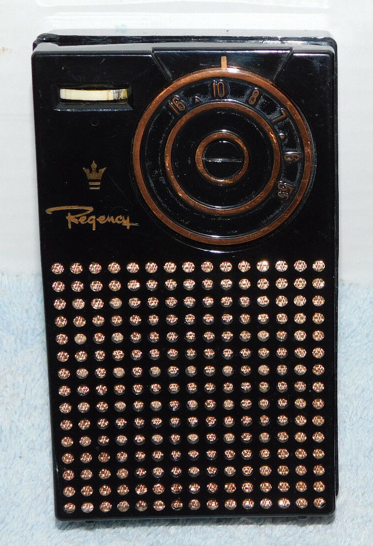
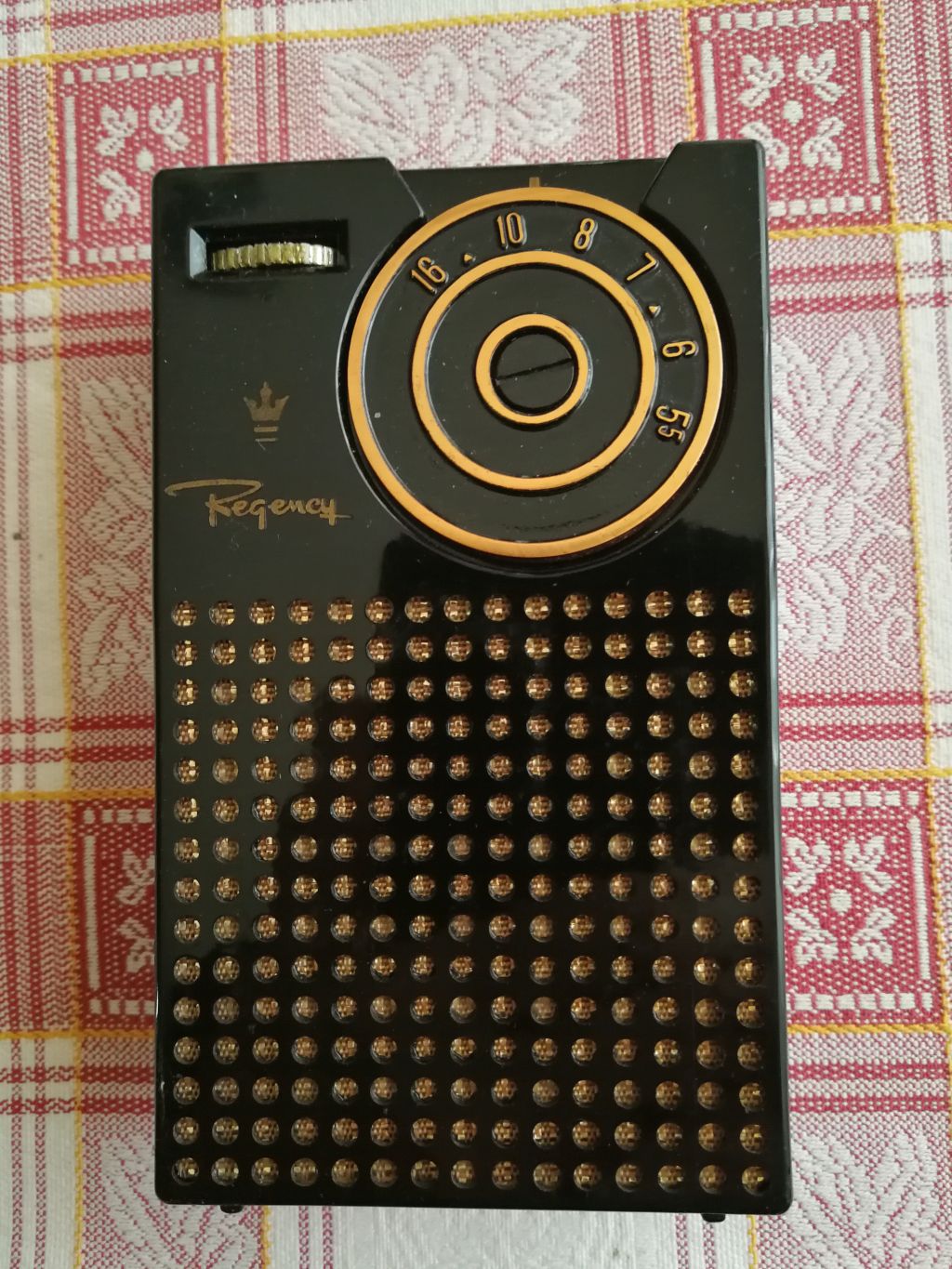
TR1-G Medium wave transistor radio U.S.A. 1955 |
|
 Description
Restoration
Description
Restoration |
 |
 Descrizione
Restauro
Descrizione
Restauro |
|||||||
|
|
|||||||||
 |
 |
 |
 |
||||||
|
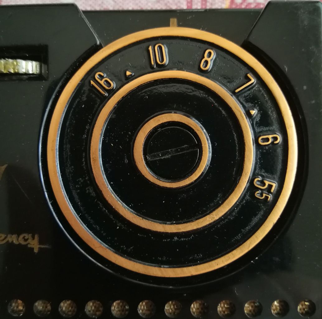
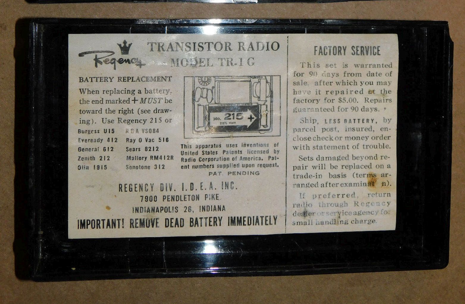
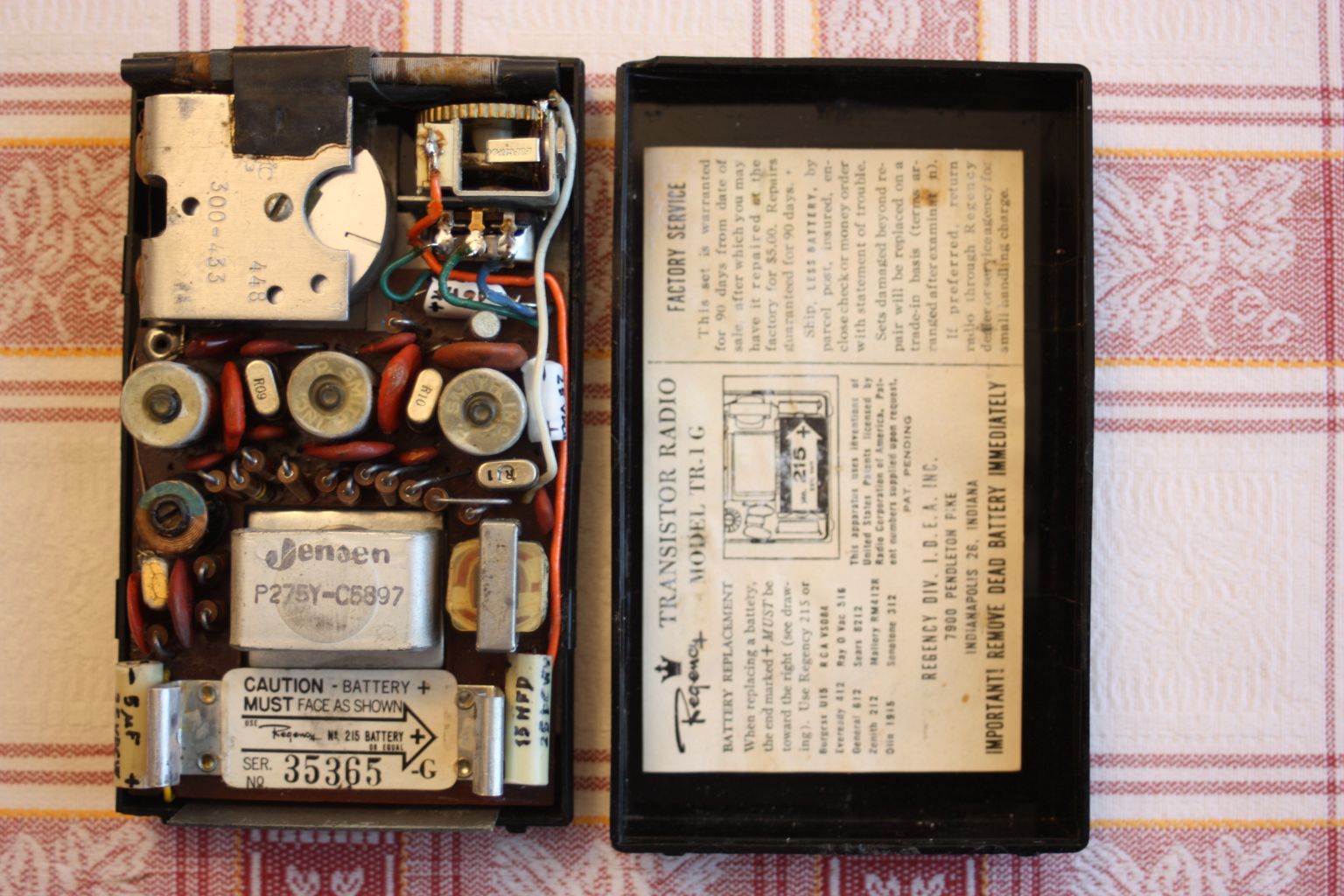
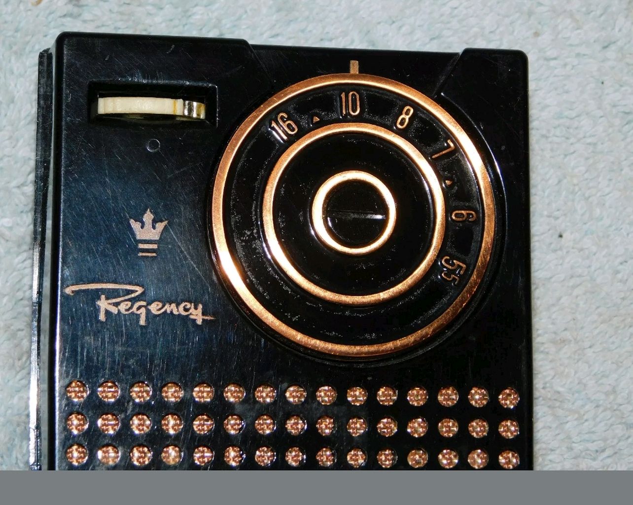
About one year later, in the last months of 1955 and after many copies built, the model had some changes and became TR1-G. The wiring diagram of the G model always used four transistors (235_TI, R06_TI, R10_TI, R11_TI), and followed almost everything of the predecessor with minimal differences, one of which was that to increase a bit the output power, the new PNP transistor (R11_TI) was used in the audio final stage instead of the previous NPN (TI210). Using a circuit equipped with only four transistors, the Regency TR1 was not particularly sensitive, the audio quality was not excellent and for the time this portable radio was rather expensive ($49.95), but thanks to its small size, the low cost of the batteries and the new technology that contained the radio was immediately successful and constituted the beginning of an era. The idea of producing portable radios with the new technology was quickly copied and implemented in the following years by many other American companies, such as RCA, Raytheon, Zenith and General Electric (see here a General Electric 676) and also by a new Japanese company, Sony, which in a few years became the world's largest manufacturer of transistor radios (a Sony mod. TR-610 can be seen here). Historical note: It is interesting to note that all the Medium Wave radios built in the United States from 1951 to 1963 had to be realized with two small triangles or with the abbreviation CD on the tuning dial, at frequencies of 640 and 1240 kHz. The Regency tuning dial also fulfilled this obligation. (For more information follow this link). |
|||||||||
|
Return to top of page
|
|||||||||
 |
 |
 |
 |
||||||
|
L'anno successivo, negli ultimi mesi del 1955 e dopo molti esemplari costruiti, il modello subì alcune modifiche e divenne TR1-G. Lo schema elettrico del modello G utilizzava sempre quattro transistor (235_TI, R06_TI, R10_TI, R11_TI), e ricalcava quasi in tutto quello del predecessore con minime differenze, una delle quali era che per incrementare un po' la potenza d'uscita, nello stadio finale audio veniva utilizzato il nuovo transistor PNP (R11_TI) anziché il precedente NPN (TI210). Utilizzando un circuito equipaggiato con solo quattro transistor la Regency TR1 non era particolarmente sensibile, la qualità dell'audio non era eccelsa e per l'epoca questa radio portatile era piuttosto costosa (49,95 $), ma per merito delle piccole dimensioni, del basso costo delle batterie e della nuova tecnologia che conteneva la radio ebbe subito successo e costituì l'inizio di un'epoca. L'idea di produrre radio portatili con la nuova tecnologia venne rapidamente copiata e implementata negli anni successivi da molte altre aziende statunitensi, come RCA, Raytheon, Zenith e General Electric (vedi qui una General Electric 676) e anche da una nuova ditta Giapponese, la Sony, che in pochi anni diventò il maggiore produttore mondiale di radioline a transistor (una Sony mod. TR-610 è visibile qui). Nota storica: E' interessante notare che sulle scale parlanti delle radio a Onde Medie costruite negli U.S.A dal 1951 al 1963 dovevano esserci due triangolini o la sigla CD in corrispondenza delle frequenze di 640 e 1240 kHz. Anche la scala di sintonia della Regency ottemperava a questo obbligo. (Per maggiori informazioni seguire questo link). |
|||||||||
 |
 |
 |
 |
||||||
 |
 |
 |
 |
||||||
|
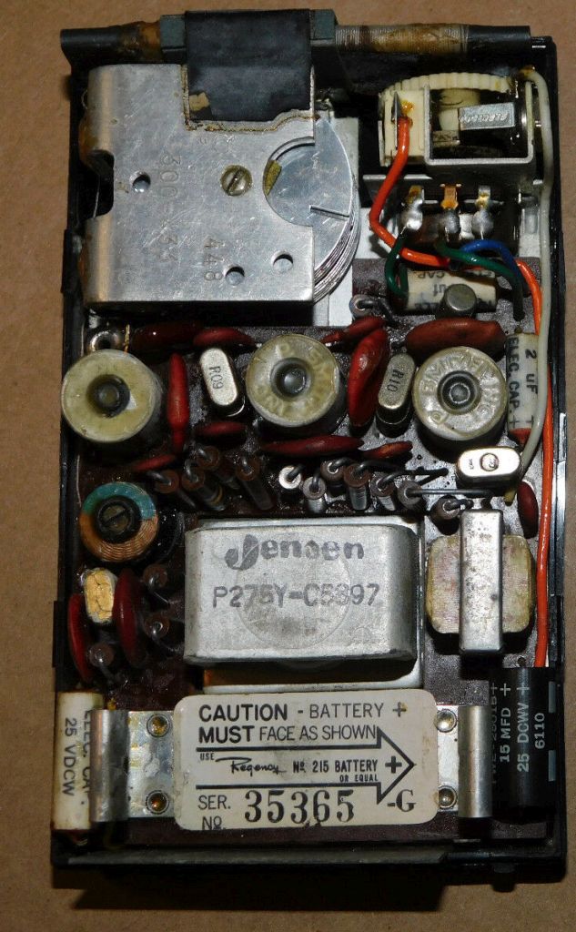
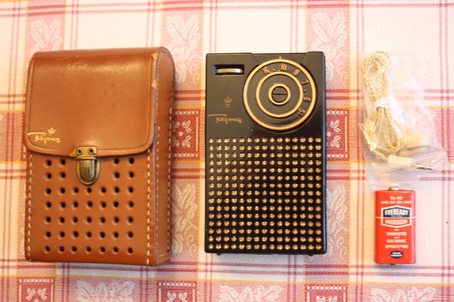
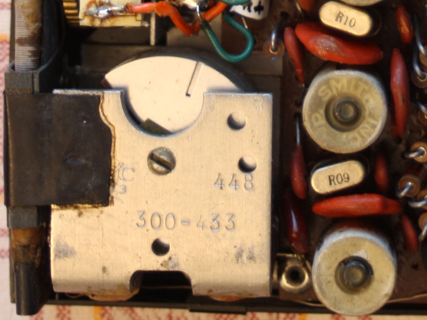
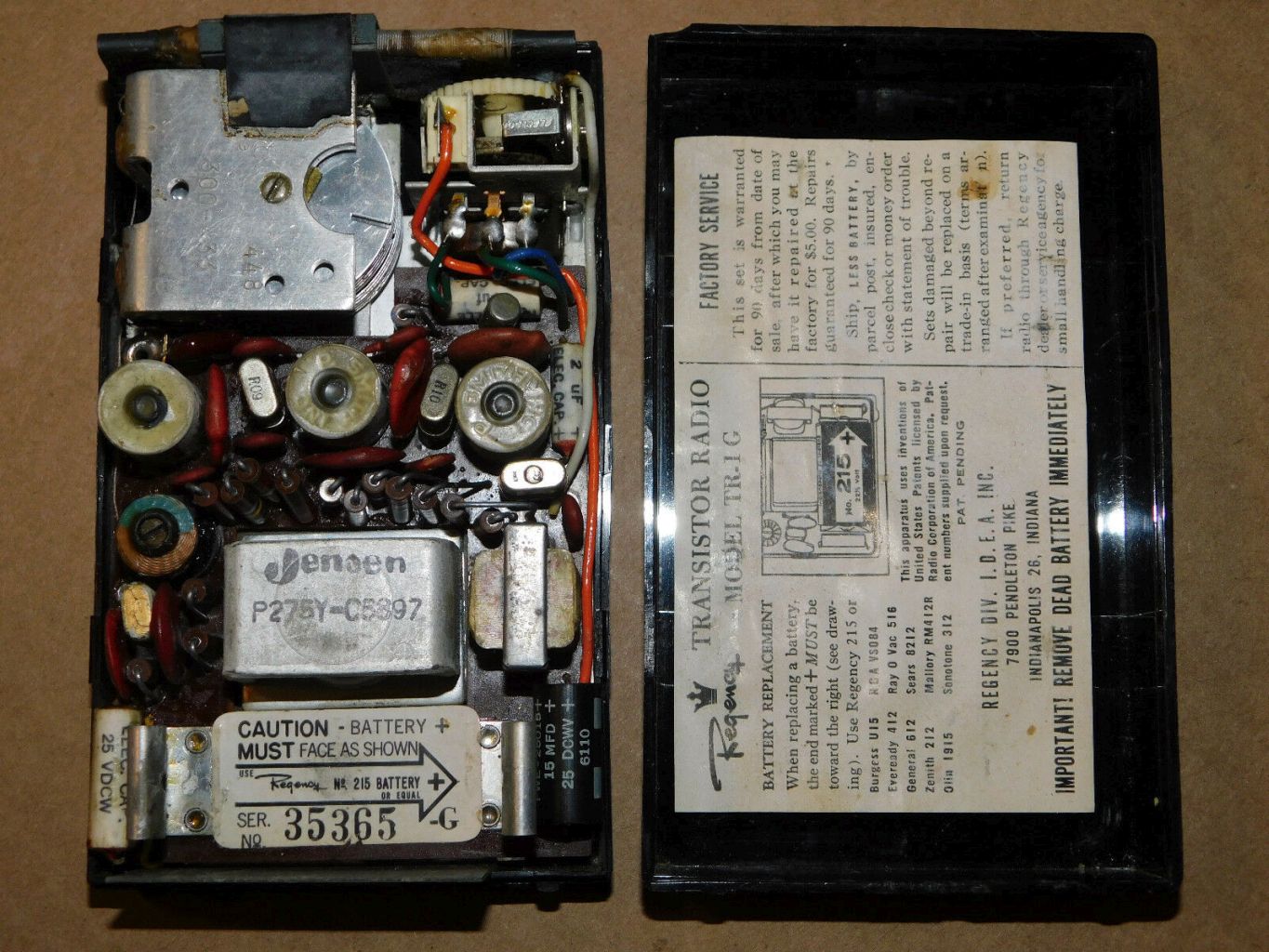
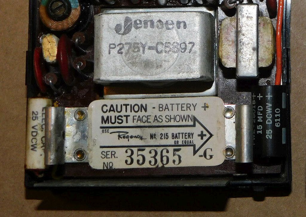
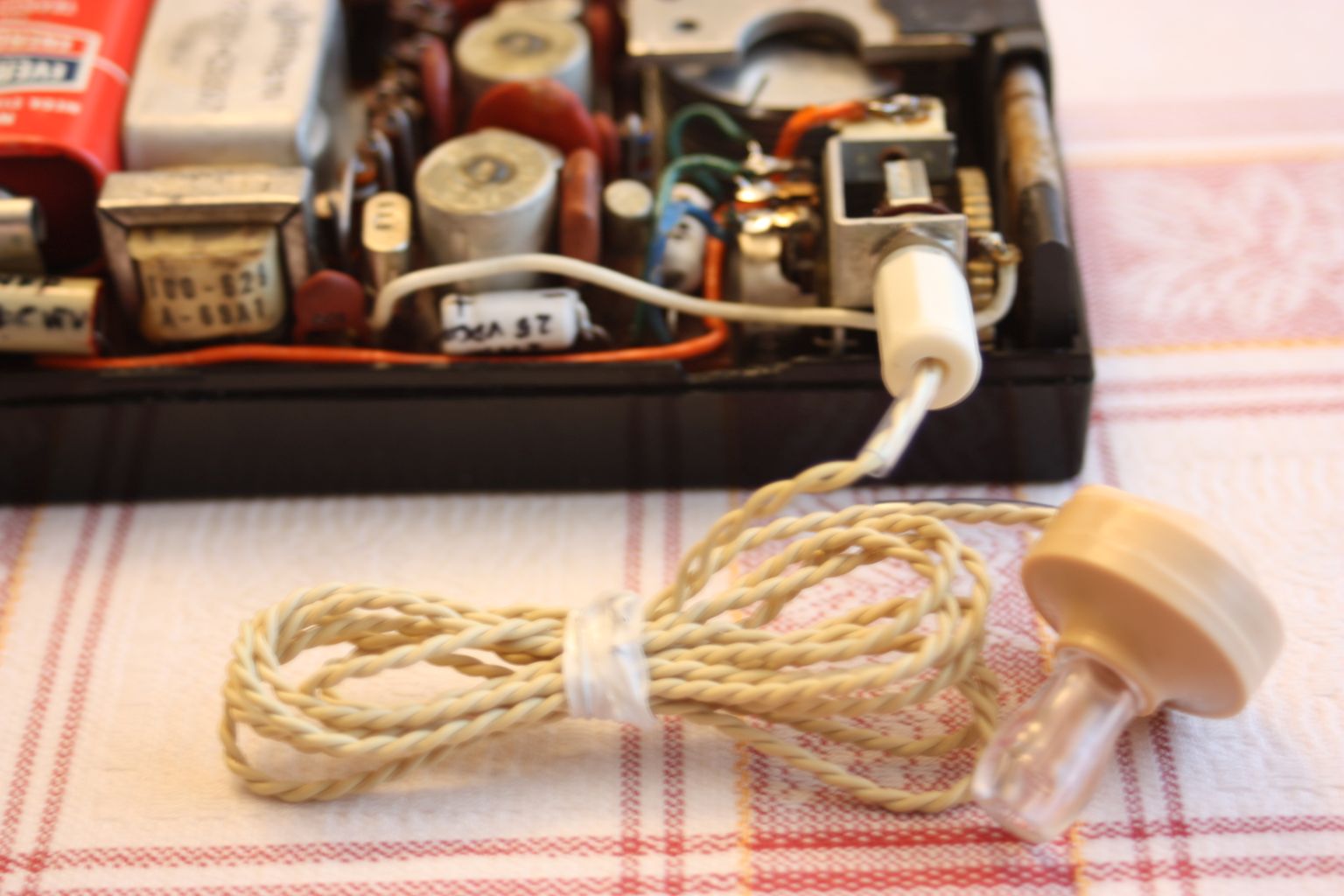
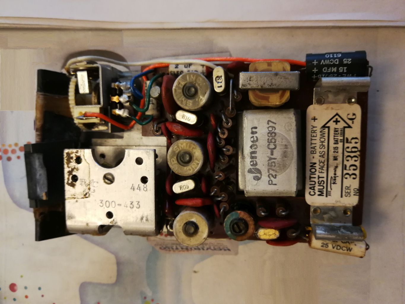
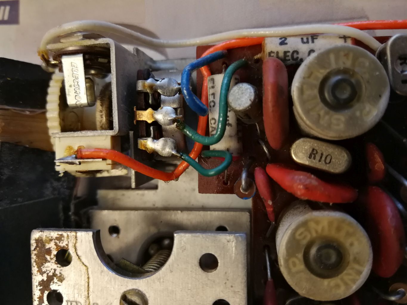
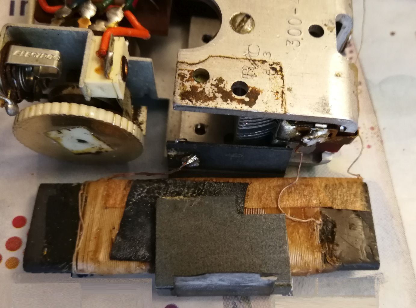
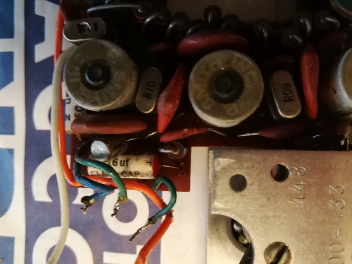
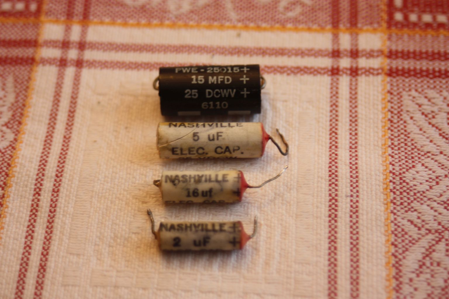
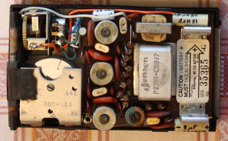
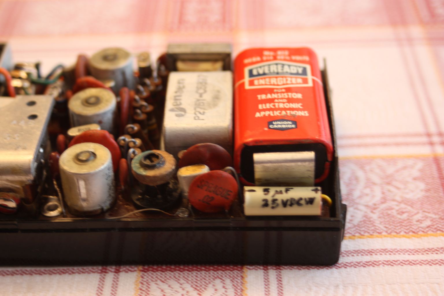
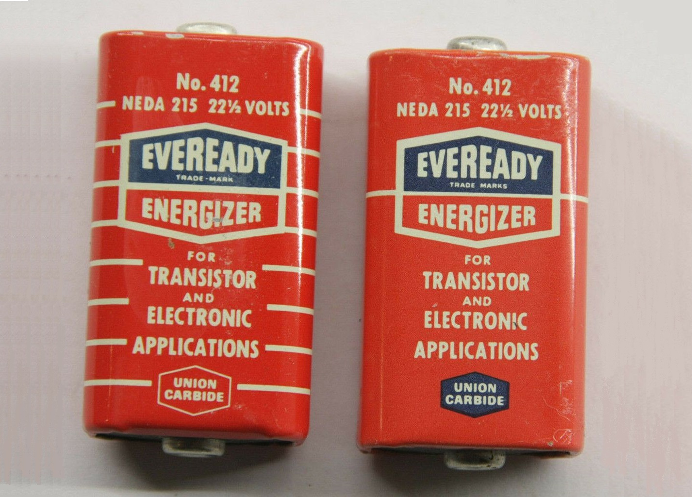
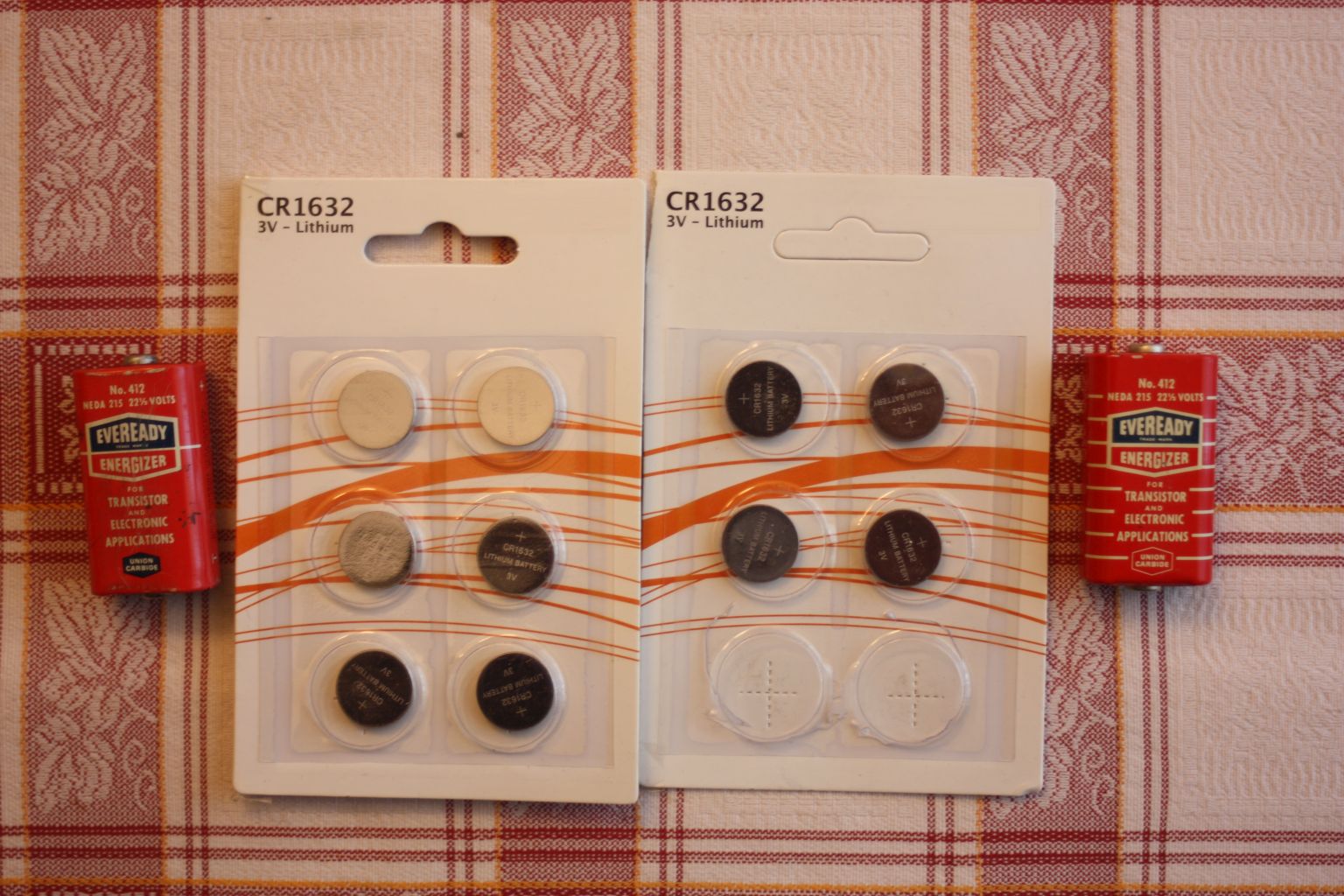
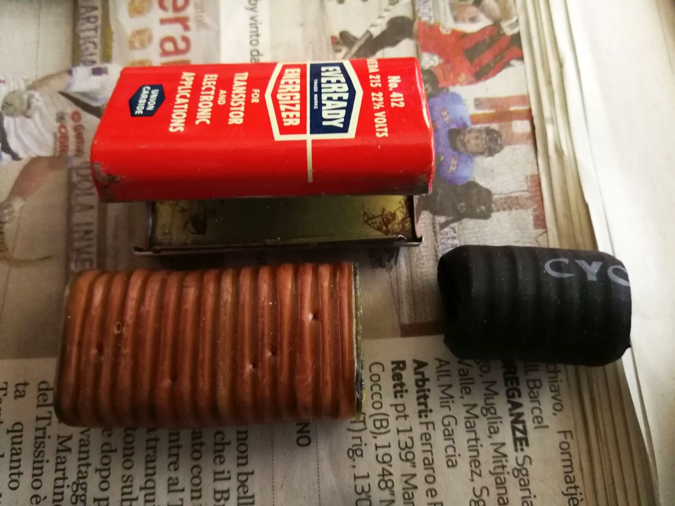
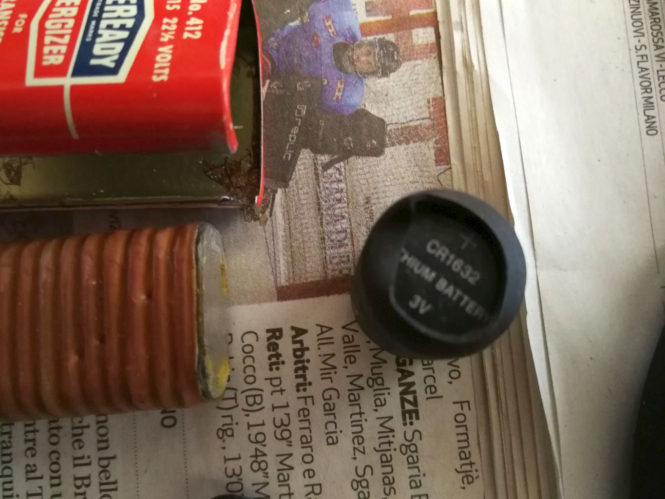
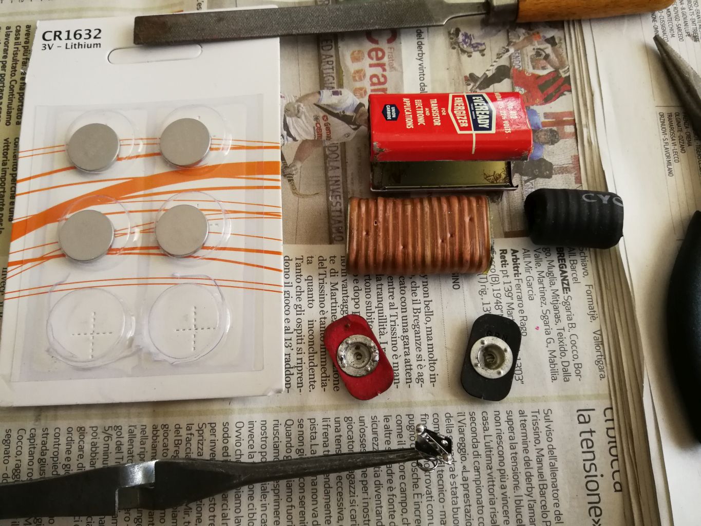
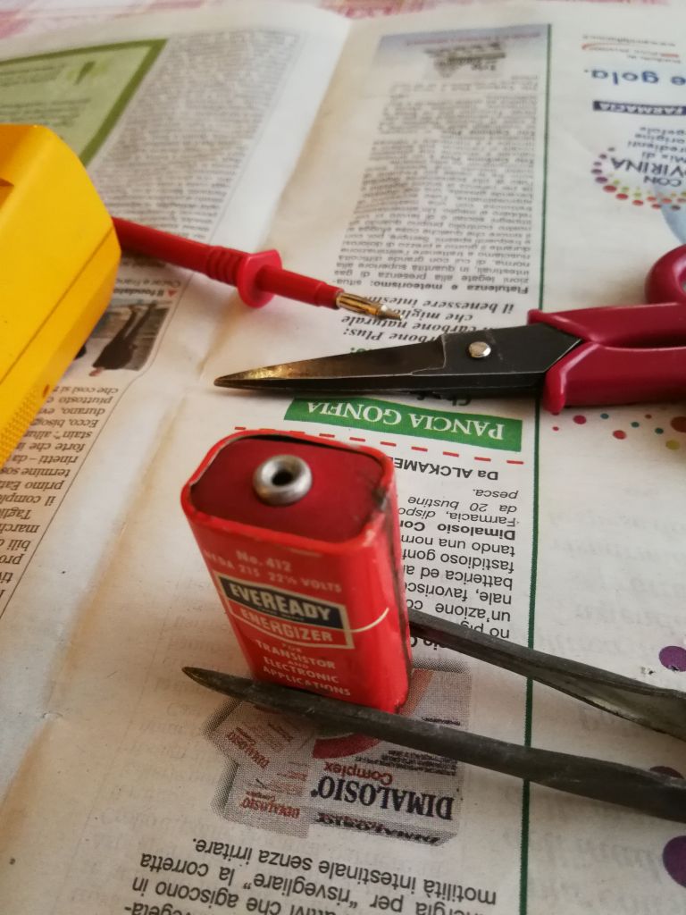
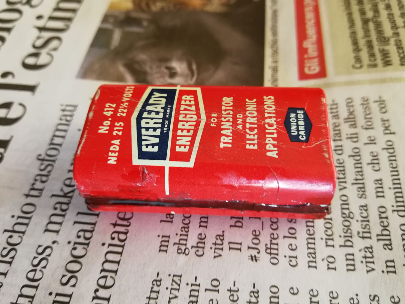
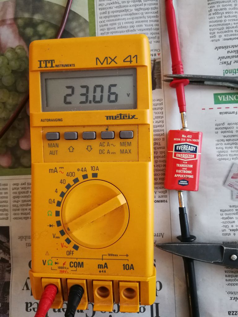
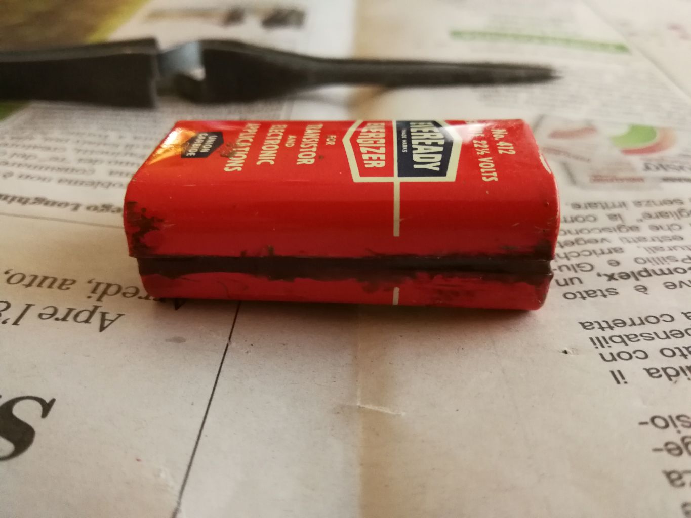
Once I connected the Regency to the power supply, I setted it to the minimum voltage and I gave power gradually, adjusting the potentiometer until it reached 20 Volts. I was amazed! After 64 years the radio still gave some signs of life. There was a little rustle from the speaker and faint whistles were heard when turning the dial knob. Could I be satisfied? Absolutely not, this example of the first transistor radio deserved better. Here the Regency TR1-G schematic. Previous experiences had taught me that to revive an old receiver first of all it was necessary to replace the capacitors, especially electrolytic ones, which after so many years had certainly deteriorated. But the aesthetics were at stake and I was reluctant to touch the original components. In each case the desire to put the radio back into operation was pressing and led me to remove and measure the four electrolytic capacitors present in the circuit, respectively C1, C2, C3 and C4. The original capabilities were significantly deteriorated so I replaced them with modern components, and as the new ones were smaller, I managed to disguise them by inserting the new ones into some ivory-white plastic tube spacers found in my miracle drawer. During the replacement I tried to respect the original values as much as possible: 2.2 MF instead of 2 MF; 4.7 MF instead of 5 and 22 MF instead of the original 15 and 16 MF. Since the nominal supply voltage was 22.5 Volts, I thought it wise to overabund with the working voltages of the new capacitors, choosing those capable of withstanding at least 35 DCWV. I replaced the components using great care, taking photos and marking on a sheet of paper the color of the wires that I had to unsolder, then I separated the printed circuit from the chassis. Once the four components were installed, soldered and reassembled everything, I used a deoxidizer spray on the potentiometer and on the power on switch to restore the contacts, then I connected the power supply respecting the polarity and gave voltage. This time with 20 Volts the rustle coming out from the speaker was much louder and by turning the tuning knob with understandable nervousness I was able to pick up different medium wave radio stations in the clear even though it was early afternoon, when the propagation in this frequency range it is still limited. The stations listened to were mostly foreign, but among other signals I was also able to receive the weak one from RAI which in my Region broadcasts with 5 kW at 936 KHz. The radio worked, it was not necessary to replace anything else and not even to proceed with the calibration of the intermediate frequency transformers at 262 kHz, thus avoiding the risk of breaking the fragile ferrite cores. The emotion was so great that I celebrated the success with a good espresso. Emboldened by the victory, I wanted to complete the work. Through an online purchase I got a pair of exhausted Eveready No. 412 batteries (No. 412 batteries are equivalent to the original Regency No. 215), I opened them by making a horizontal cut on one side, I removed the original battery from each one and in its place with a little patience I forced inside seven 3 Volt CR1632 lithium button cells placed in series, held together by a piece of heat shrink tubing and pressed against the contacts with two springs stolen from an old AA battery holder. Once the Eveready casing was sealed with epoxy glue, the total measured voltage turned out to be something more than 23 volts, which dropped to 20 under load, but more than enough to run the Regency TR1-G, which thus became a portable pocket radio again. © IK3HIA 2020 |
|||||||||
 |
 |
 |
 |
||||||
 |
 |
 |
 |
||||||
|
Return to top of page
|
|||||||||
|
Una volta collegata la Regency all'alimentatore, l'ho regolato al minimo e ho dato tensione, ruotando un po' alla volta il potenziometro fino a raggiungere i 20 V. Sono rimasto stupito! Dopo 64 anni la radio dava ancora qualche segno di vita. Dall'altoparlante proveniva un po' di fruscio e ruotando la manopola di sintonia si captavano dei deboli fischi. Potevo accontentarmi? Assolutamente no, questo esemplare della prima radio a transistor meritava di meglio. Lo schema della Regency TR1-G. Precedenti esperienze mi avevano insegnato che per far rivivere un vecchio ricevitore bisognava per prima cosa sostituire i condensatori, specialmente quelli elettrolitici, i quali dopo tanti anni erano sicuramente deteriorati. Ne andava però dell'estetica ed io ero restio a toccare i componenti originali. In ogni caso il desiderio di rimettere in funzione la radio era pressante e mi ha indotto a togliere e misurare i quattro condensatori elettrolitici presenti nel circuito, rispettivamente C1, C2, C3 e C4. Le capacità originali erano decisamente deteriorate e le ho sostituite con componenti moderni, e siccome quelli nuovi erano più piccoli, sono riuscito a camuffarli inserendo i nuovi dentro alcuni distanziatori a tubetto di plastica color bianco-avorio trovati nel mio cassetto dei miracoli. Durante la sostituzione ho cercato di rispettare al massimo i valori originali: 2,2 MF al posto di 2 MF; 4,7 MF invece di 5 e 22 MF al posto di 15 e di 16 MF originali. Visto che la tensione di alimentazione nominale era di 22,5 Volt, ho ritenuto saggio sovrabbondare con le tensioni di lavoro dei nuovi condensatori, scegliendo quelli in grado di sopportare come minimo 35 Volt lavoro. Ho sostituito i componenti usando grande cautela, facendo foto e segnandomi su un foglio il colore dei fili che dovevo dissaldare, poi ho separato il circuito stampato dallo chassis. Una volta installati i quattro componenti, rifatte le saldature e riassemblato il tutto, ho usato dello spray disossidante sul potenziometro e sull'interruttore di accensione per ripristinarne i contatti, poi ho collegato l'alimentatore rispettando le polarità e dato tensione. Questa volta con 20 Volt il fruscio che usciva dall'altoparlante era molto più forte e ruotando con comprensibile nervosismo la manopola di sintonia ho potuto captare in chiaro diverse stazioni radio in onde medie pur essendo inizio del pomeriggio, quando la propagazione in tale gamma di frequenze è ancora limitata. Le stazioni ascoltate erano per lo più straniere, ma tra gli altri segnali ho potuto ricevere anche quello debole della RAI che nella mia Regione trasmette con 5 kW a 936 kHz. La radio funzionava, non è stato necessario sostituire nient'altro e nemmeno procedere alla taratura dei trasformatori di media frequenza a 262 kHz, evitando così il rischio di rompere i fragili nuclei di ferrite. L'emozione è stata grande tanto che ho festeggiato il successo con un buon caffè espresso. Imbaldanzito dalla vittoria ho voluto completare l'opera. Tramite un acquisto on-line mi sono procurato un paio di batterie Eveready tipo 412 esaurite (le batterie tipo 412 sono equivalenti alle Regency No. 215 originali), le ho aperte eseguendo un taglio orizzontale su una fiancata, ho tolto da ognuna la batteria originale e al suo posto con un po' di pazienza vi ho infilato dentro sette pile a bottone al litio tipo CR1632 da 3 Volt poste in serie, tenute assieme da uno spezzone di guaina termorestringente e pressate contro i contatti con due molle rubate a un vecchio porta pile AA. Una volta rinchiuso l'involucro della Eveready con della colla epossidica la tensione totale misurata è risultata qualcosa di più di 23 V che sotto carico scendevano a 20, ma più che sufficienti per far funzionare la Regency TR1-G che in tal modo è ridiventata una radio portatile tascabile. © IK3HIA 2020 |
|||||||||
 |
 |
 |
 |
||||||
 |
 |
 |
 |
||||||
|
Return to top of page
|
|||||||||
|
|
Return to: IK3HIA home page |
|
Return to: Transistor Radio |
|
Go to: Transistor diagrams |