 |
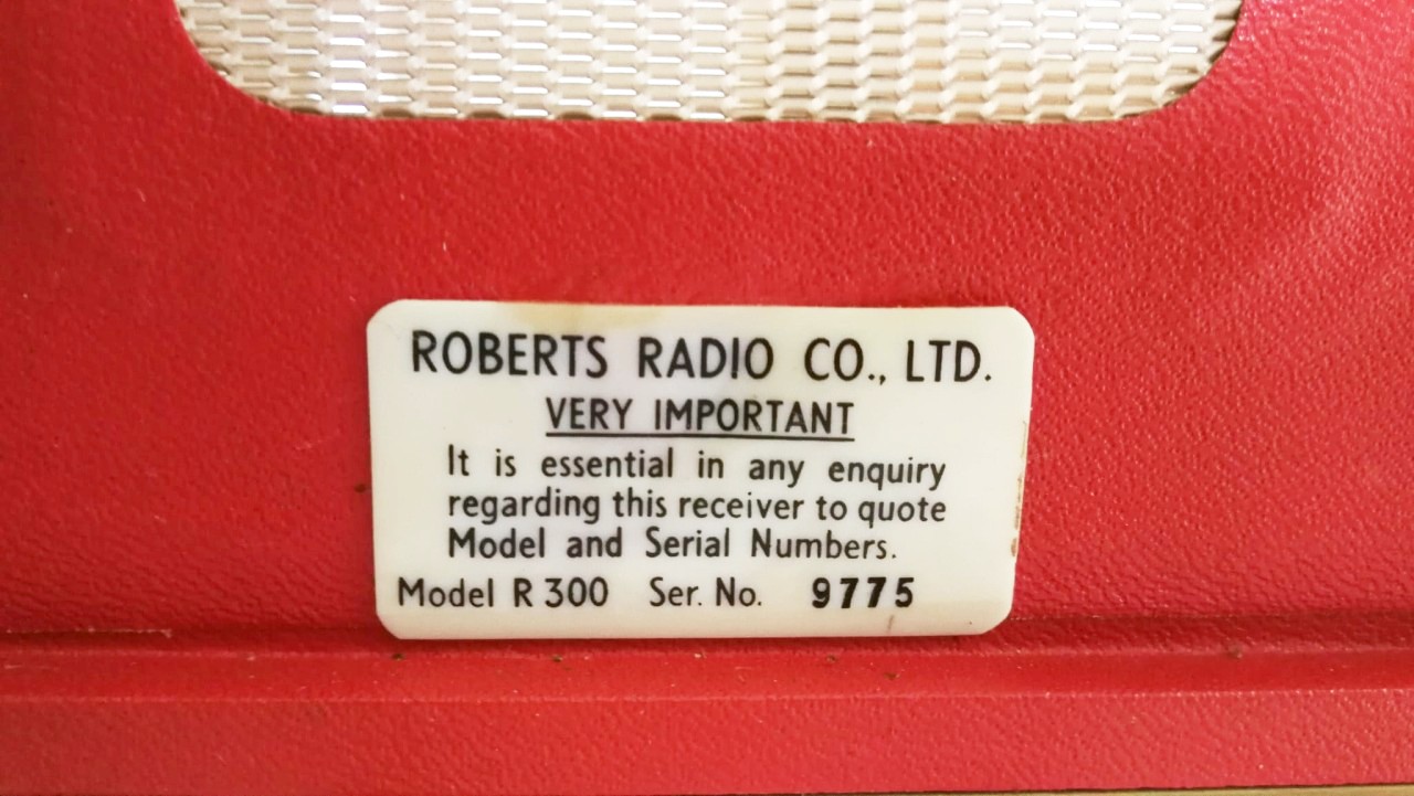
Roberts R300 - U.K. 1964 |
|
 Description
Repair
Description
Repair |
Click to view

|
Descrizione Riparazione |
|||||
|
|
|||||||
 |
 |
 |
 |
||||
 |
 |
 |
 |
||||
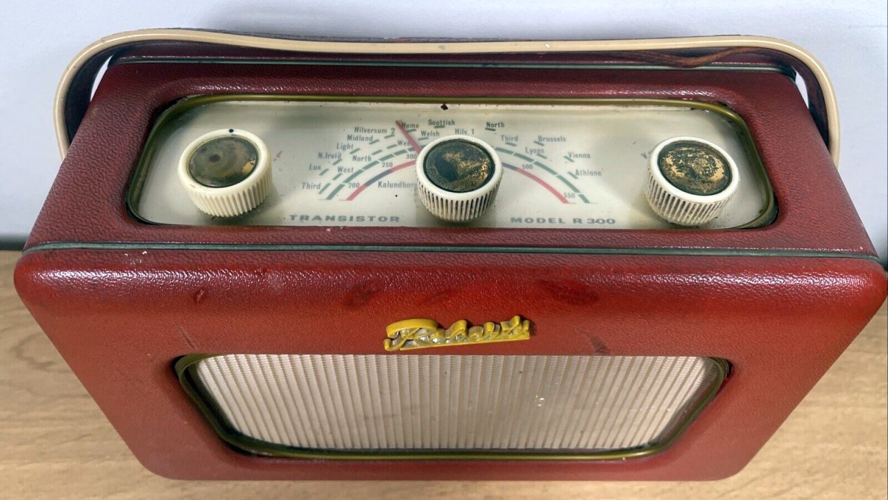
 La Roberts R300 è stato il terzo modello di radio
portatile a
transistor prodotto dalla ditta inglese Roberts Radio Co. Ltd. e fu
presentata nel 1964. Come le precedenti
RT1 e
R200, la R300 era un apparecchio robusto realizzato
con componenti discreti montati su circuito stampato senza velleità di
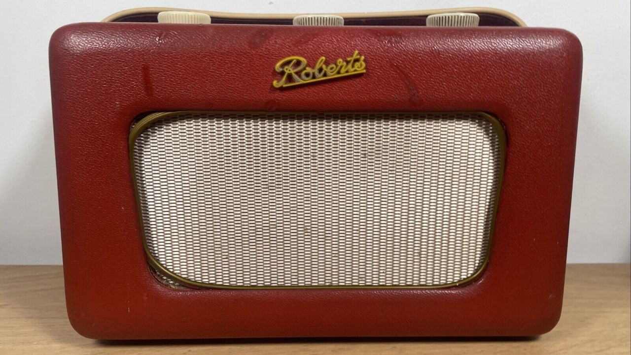
miniaturizzazione. La radio utilizzava lo stesso elegante
mobiletto in legno ricoperto in finta pelle di vari colori già
ampiamente utilizzato nelle radio portatili a valvole
tipo R55
e
R66
prodotte alla metà degli anni '50 e nei due più recenti modelli a
transistor.
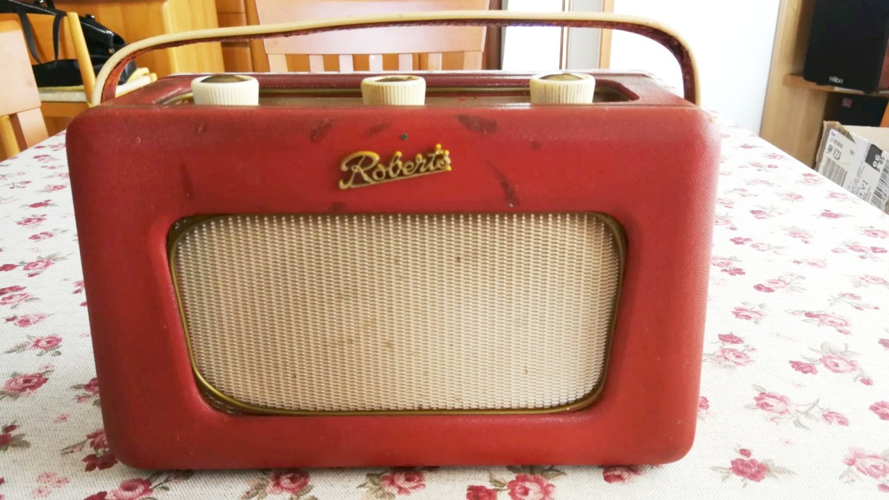
La Roberts R300 è stato il terzo modello di radio
portatile a
transistor prodotto dalla ditta inglese Roberts Radio Co. Ltd. e fu
presentata nel 1964. Come le precedenti
RT1 e
R200, la R300 era un apparecchio robusto realizzato
con componenti discreti montati su circuito stampato senza velleità di
miniaturizzazione. La radio utilizzava lo stesso elegante
mobiletto in legno ricoperto in finta pelle di vari colori già
ampiamente utilizzato nelle radio portatili a valvole
tipo R55
e
R66
prodotte alla metà degli anni '50 e nei due più recenti modelli a
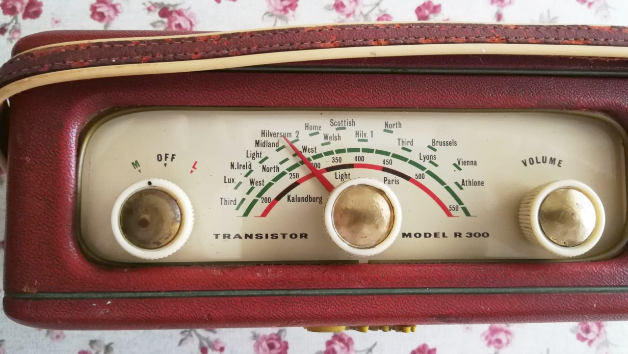
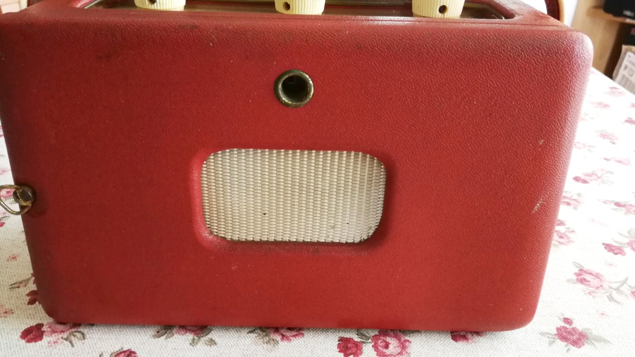
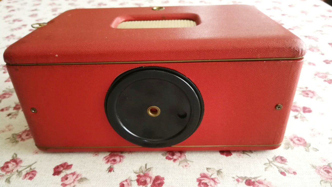
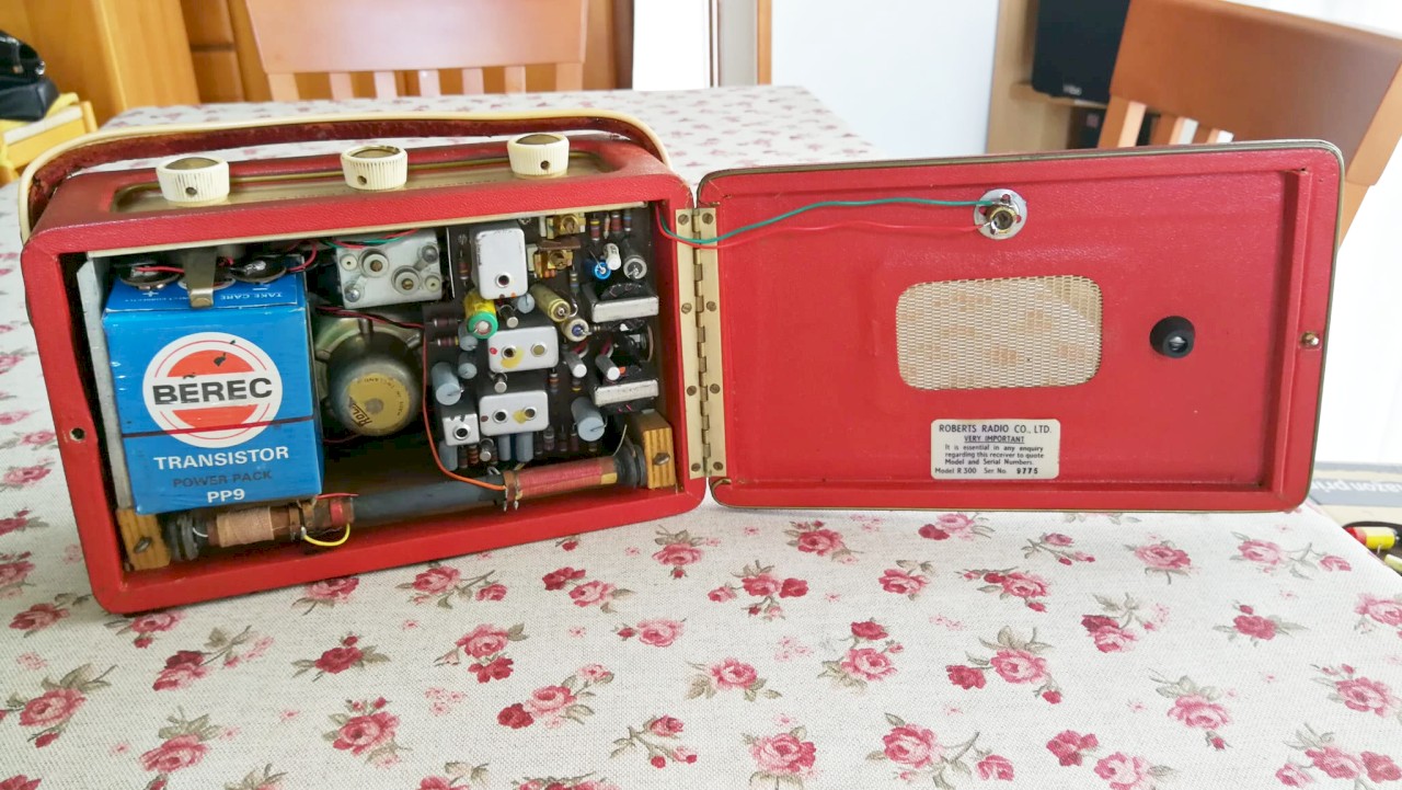
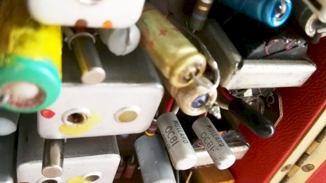
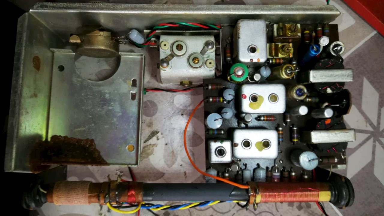
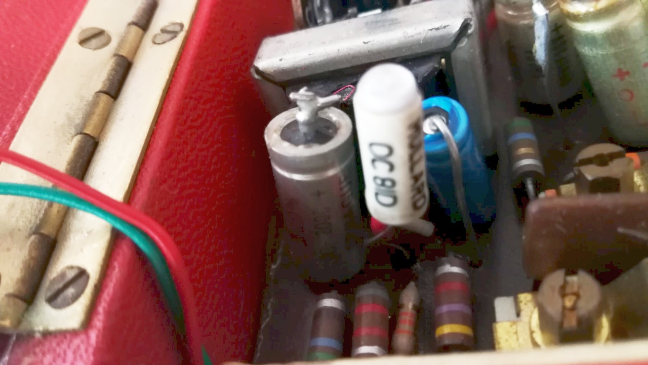
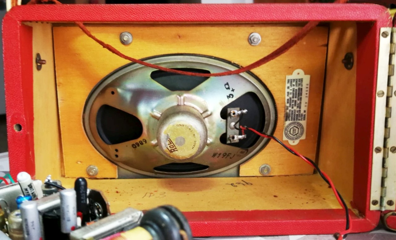
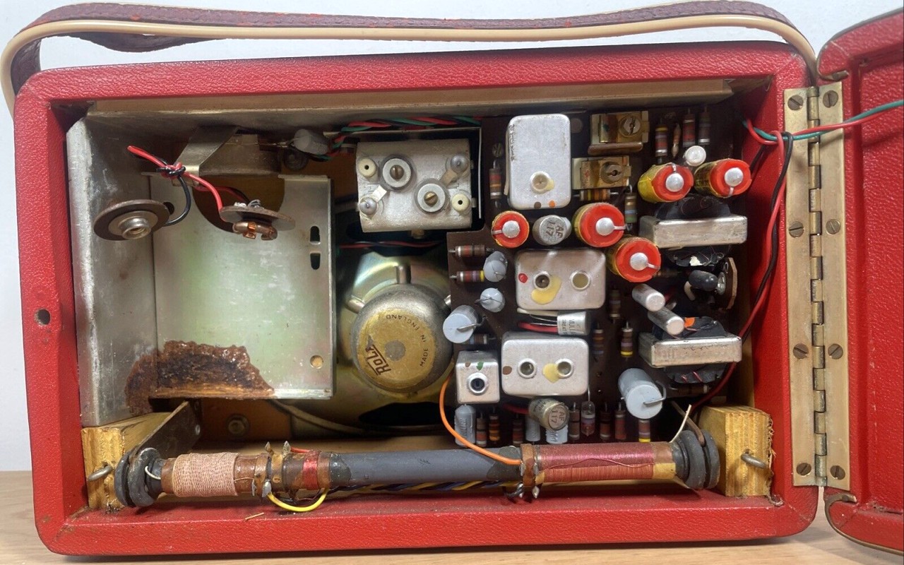
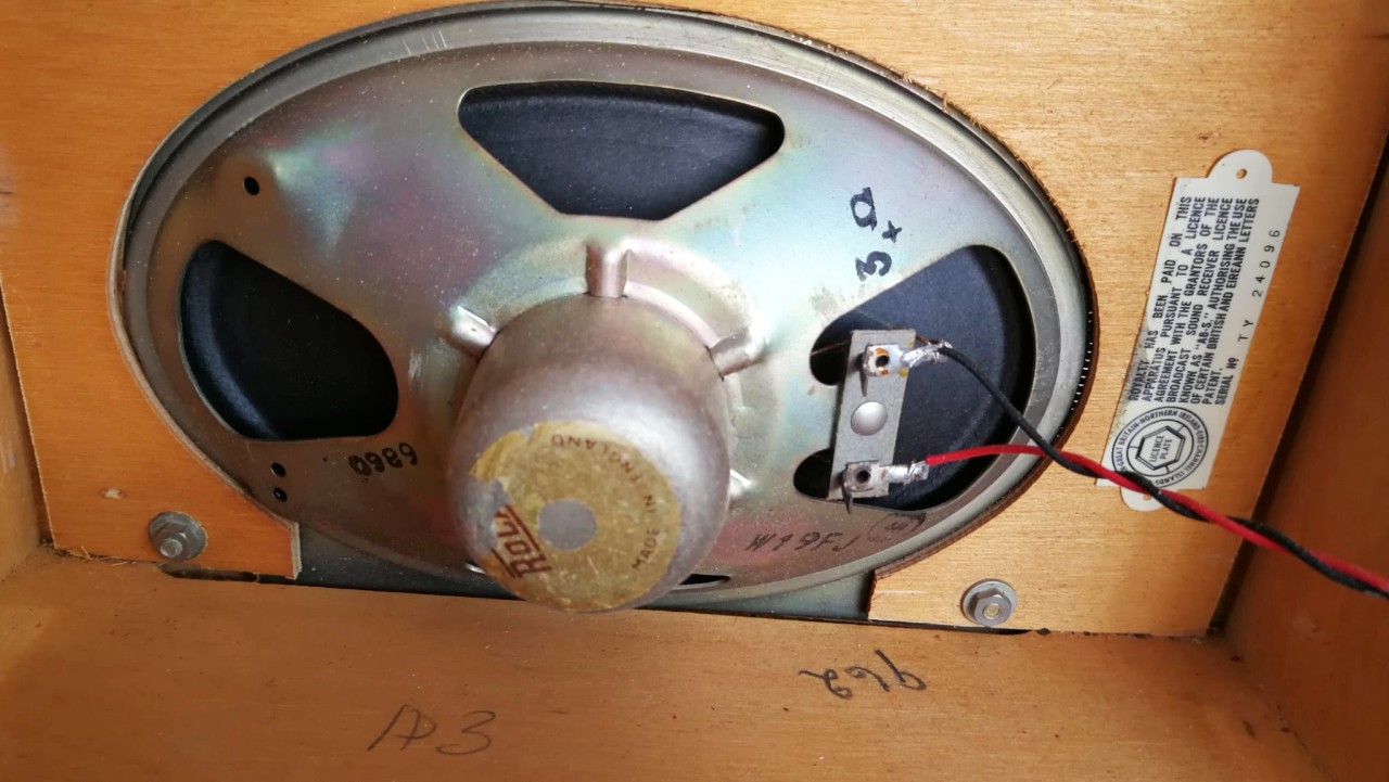
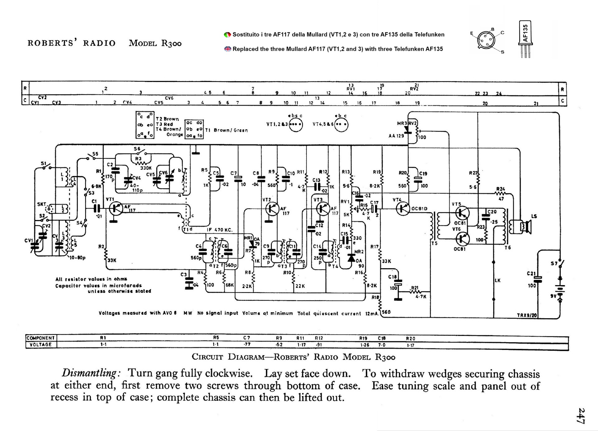
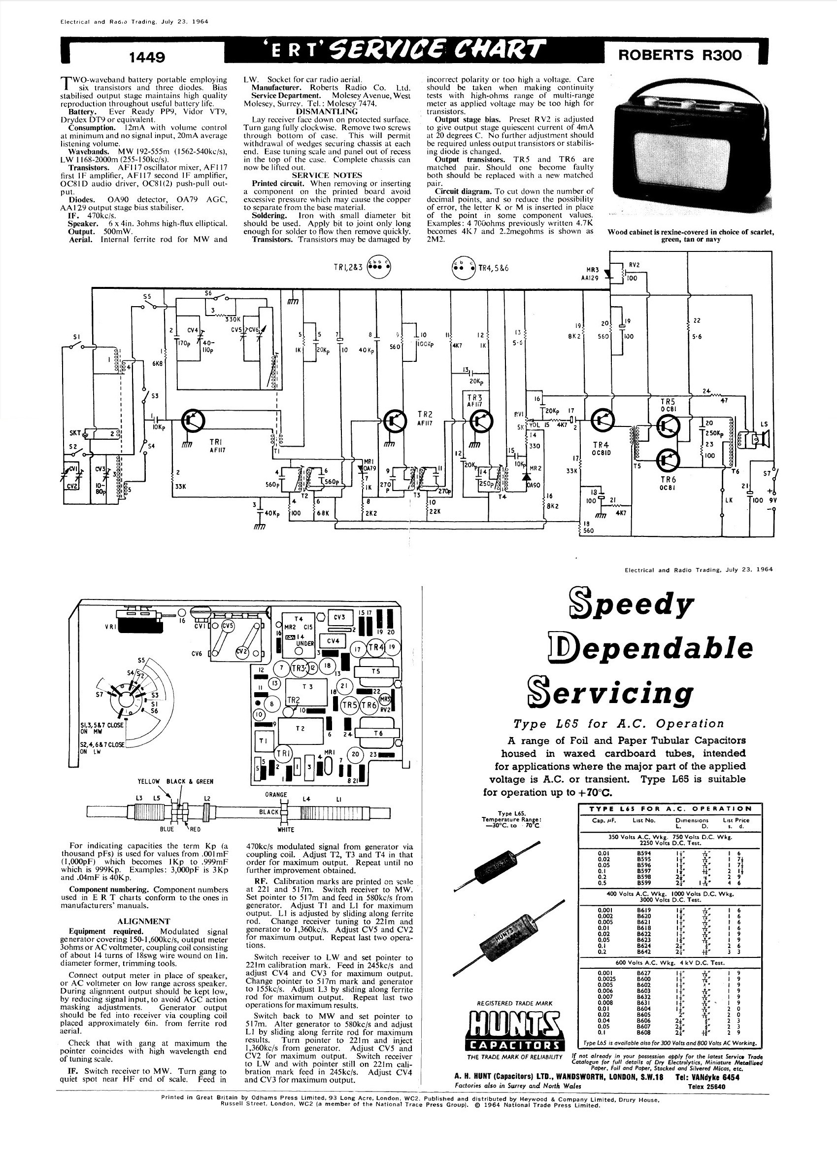
transistor.Il circuito elettrico adottato dalla Roberts era quello classico, con amplificatore-oscillatore di Alta Frequenza, due stadi di Frequenza Intermedia, rivelatore a diodo al germanio, preamplificatore di Audio Frequenza e stadio di potenza ad Audio Frequenza con trasformatori e Push-Pull di transistor PNP. La R300 utilizzava la serie di transistor al germanio prodotti dalla Mullard (AF117, AF117, AF117, OC81D, OC81, OC81, un AA129 utilizzato come stabilizzatore e due diodi al germanio: OA79 e OA90), serie che era già stata impiegata dalla Roberts anche negli ultimi esemplari di R200 dalla matricola 70000 in poi. La ricezione copriva la gamma delle Onde Medie da 539 a1594 KHz e le Onde Lunghe da 152 a 265 KHz. La Frequenza Intermedia risuonava a 470 KHz. Come per i modelli precedenti, per sfruttare in maniera ottimale la direzionalità dell'antenna, la R300 era dotata alla base di un disco di plastica girevole, il disco permetteva la rotazione del ricevitore per captare meglio il segnale. Per l'eventuale utilizzo del ricevitore a bordo di un'auto, nel pannello posteriore era prevista una presa d'antenna tipo autoradio. L'alimentazione era fornita da una grossa batteria da 9 V tipo PP9 che assicurava una lunga autonomia. La resa acustica della R300 era buona sia per merito dell'ottimo mobiletto in legno sia per l'altoparlante ellittico Rola da 10x15 cm con impedenza di 3 Ohm. Le dimensioni della R200 erano: 23 x 15 x 10 cm e il peso era di 1.7 kg senza batteria. IK3HIA © 2025. |
|||||||
 |
 |
 |
 |
||||
 |
 |
 |
 |
||||
|
The Roberts R300 was the third model of portable transistor radio
produced by the English company Roberts Radio Co. Ltd. and was
introduced in 1964. Like the previous
RT1 e
R200,
the R300 was a robust device made with discrete components mounted on a
printed circuit board without any ambitions of miniaturization. The
radio used the same elegant wooden cabinet covered in imitation leather
of various colors already widely used in the portable valve radios type
R55 e
R66
produced in the mid-1950s and in the two most recent transistor models. The electrical circuit adopted by Roberts was the classic one, with a High Frequency oscillator-amplifier, two Intermediate Frequency stages, a germanium diode detector, an Audio Frequency preamplifier and an Audio Frequency power stage with transformers and Push-Pull of PNP transistors. The R300 used the new series of germanium transistors produced by Mullard (AF117, AF117, AF117, OC81D, OC81, OC81, an AA129 used as a stabilizer and two germanium diodes: OA79 and OA90), a series that had already been used by Roberts also in the last R200 models from serial number 70000 onwards. The reception covered the range of Medium Waves from 539 to 1594 KHz and Long Waves from 152 to 265 KHz. The Intermediate Frequency resonated at 470 KHz. As with the previous models, to optimally exploit the directionality of the antenna, the R300 was equipped with a rotating plastic disk at the base, the disk allowed the rotation of the receiver to better capture the signal. For the possible use of the receiver on board a car, a car radio-type antenna socket was provided on the rear panel. Power was supplied by a large 9 V PP9 battery that ensured a long autonomy. The acoustic performance of the R300 was good both thanks to the excellent wooden cabinet and to the 6x4 inch Rola elliptical speaker with an impedance of 3 Ohm. The dimensions of the R200 were: 9.1 x 5.9 x 3.9 inch and the weight was 3 lb 11.9 oz without battery. IK3HIA © 2025. |
|||||||
|
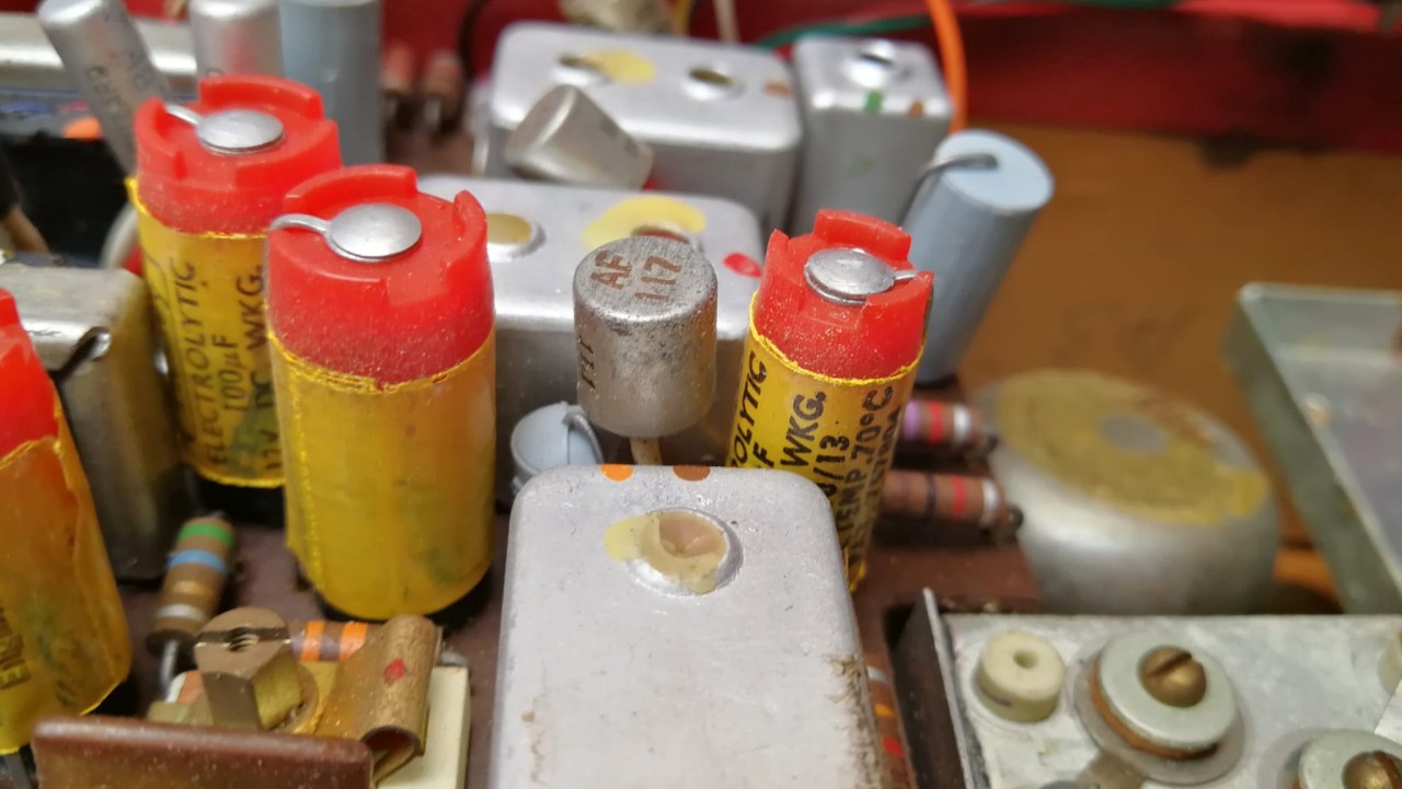
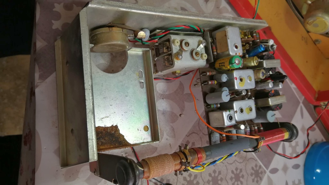
Immagini riprese
prima del restauro |
|||||||
 |
 |
 |
 |
||||
 |
 |
 |
 |
||||
|
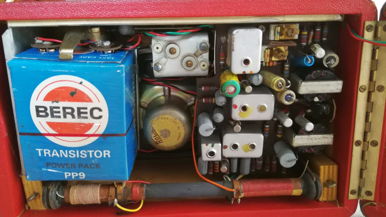
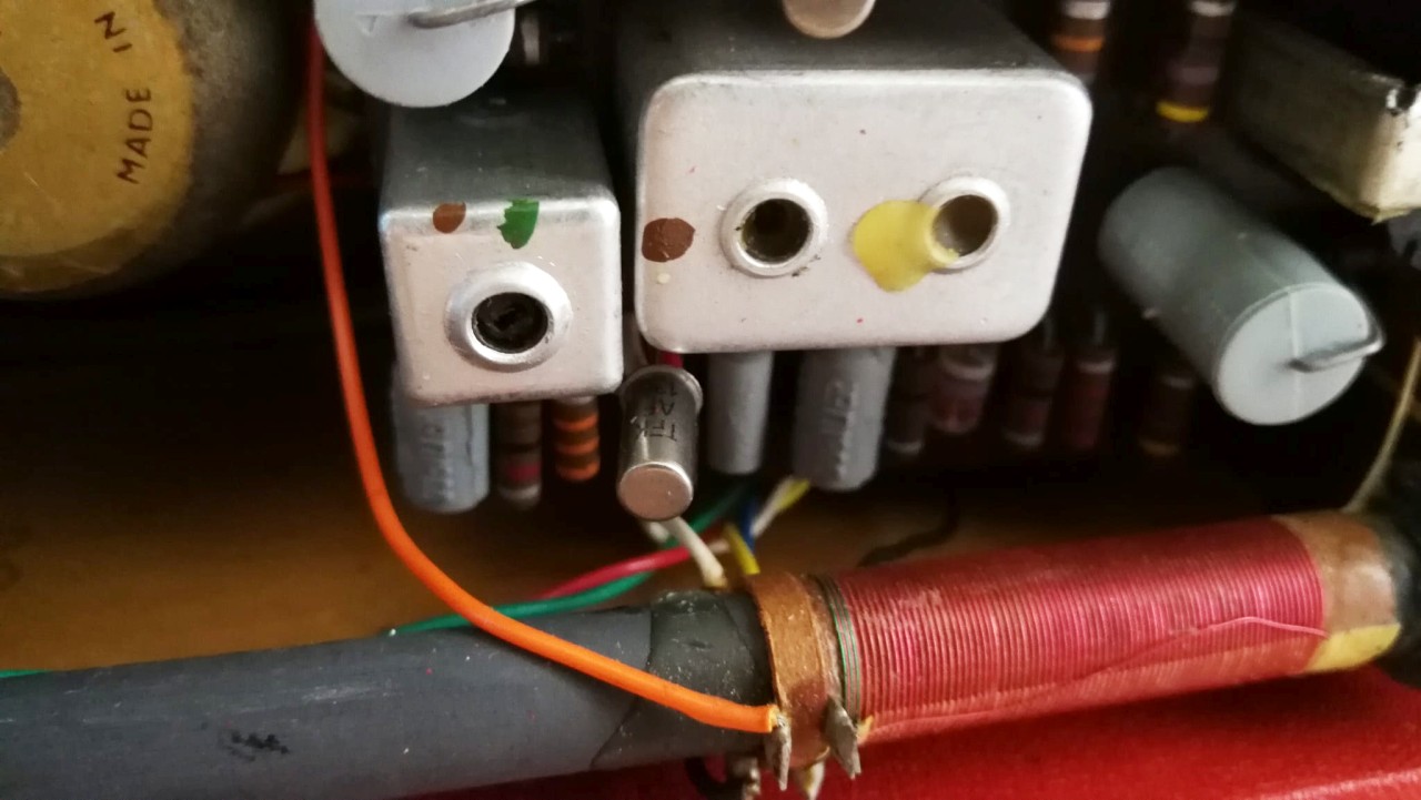
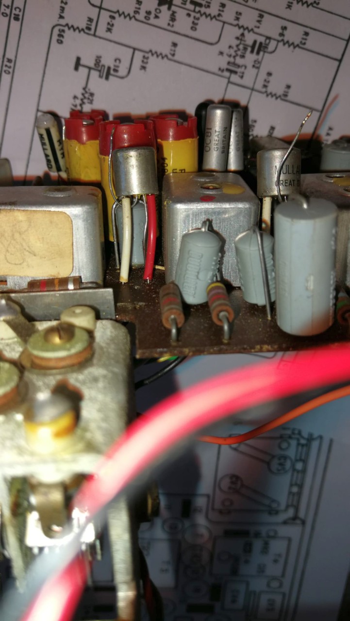
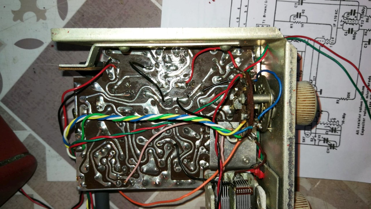
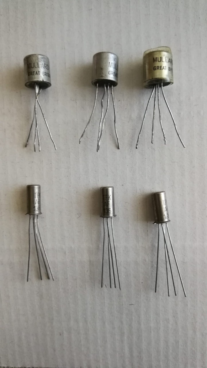
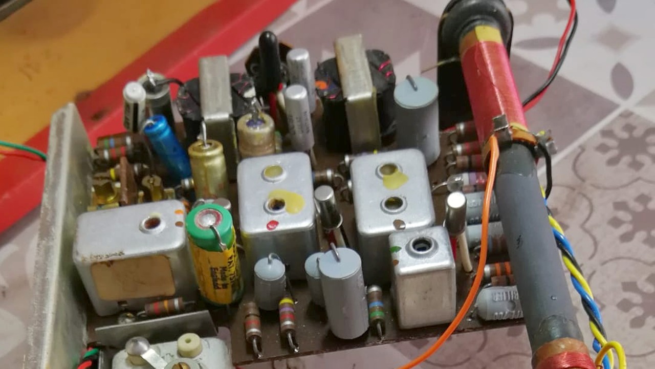
Riparazione L'esemplare di R300 che ho acquistato su ebay non era funzionante, infatti appena l'ho collegato ai 9V del mio alimentatore multitensione, ruotando il commutatore di accensione e il potenziometro del volume dall'altoparlante uscivano solo deboli scariche. Una volta esaminato lo schema elettrico ho provveduto alla sostituzione di tutti i condensatori elettrolitici con altri più moderni di pari capacità ma con superiore tensione di lavoro. Una volta completata la sostituzione ho utilizzato il mio generatore BF/RF Heathkit SG-8 per controllare i vari stadi. il Segnale di BF a 400 Hz applicato al centrale del potenziomentro del volume arrivava forte all'altoparlante, il segnale a RF di 400 kHz invece, applicato alla base del VT3 (AF117), non era udibile nemmeno alzando al massimo il controllo del volume. Tristemente ho capito che ero alla presenza di un tipico caso del noto problema dei "tin-whiskers", ovvero dei baffi di latta. Le serie di transistor di Alta Frequenza al germanio OC1xx e AF1xx prodotte all'inizio degli anni 60 avevano un involucro metallico che poteva essere collegato con un piedino alla massa del circuito, soluzione utilissima per migliorare la schermatura contro i disturbi in Alta Frequenza. Purtroppo negli anni successivi era stato scoperto che nel materiale isolante utilizzato per sigillare l'involucro con il tempo si sviluppavano a casaccio dei sottilissimi baffi di stagno, i quali andavano a cortocircuitare gli elettrodi tra loro oppure li collegavano all'involucro metallico e quindi a massa. Maggiori dettagli in lingua inglese su questo link. Per risolvere temporaneamente il problema avrei potuto "bruciare" i baffi con una moderata scarica elettrica (condensatore elettrolitico da 200 MF 50V caricato con 30 Vcc), ma poi i tin-whiskers avrebbero ripreso a crescere e dopo un po' il guasto si sarebbe ripresentato, perciò ho deciso che era consigliabile sostituire i transistor incriminati con altri al germanio tipo AF12x o successivi che non presentassero lo stesso inconveniente. Così ho fatto, e al posto dei tre vecchi AF117 ho saldato con le necessarie precauzioni tre "nuovi" AF135. Una volta alimentata la R300 con 9 V e applicato il segnale a RF di 400 kHz alla base del VT3 (adesso un AF135) il segnale in altoparlante è uscito molto forte, e così è accaduto anche quando ho iniettato il segnale sulle basi di VT2 e VT1. Subito dopo ho provato a sintonizzare alcune stazioni in Onde Medie e per festeggiare il successo ho registrato un breve video dell'evento. Visto che avevo sul tavolo il generatore Heathkit ho provveduto all'allineamento del circuito come indicato nel manuale di servizio della R300 (Service Chart). Per completare l'opera ho utilizzato lo spray disossidante sul potenziometro del volume e sul commutatore accensione-cambio gamma, dopo questi lavori la R300 era tornata a essere perfettamente funzionante ed è entrata a far parte con successo della mia collezione di radio a transistor. IK3HIA © 2025. |
|||||||
|
Back to the top of the page
|
|||||||
 |
 |
 |
 |
||||
|
Repair The R300 with serial number 9775 that I purchased on ebay was not working, in fact as soon as I connected it to the 9V of my multi-voltage power supply, by turning the power switch and the volume potentiometer, only weak discharges came out of the speaker. Once I examined the wiring diagram, I replaced all the electrolytic capacitors with more modern ones of equal capacity but with a higher working voltage. Once the replacement was complete, I used my Heathkit SG-8 BF/RF generator to control the various stages. The 400 Hz AF signal applied to the center of the volume potentiometer reached the speaker strongly, but the 400 kHz RF signal applied to the base of the VT3 (AF117) was not audible even when the volume control was turned up to the maximum. Sadly I realized that I was in the presence of a typical case of the well-known "tin-whiskers" problem. The OC1xx and AF1xx series of germanium High Frequency transistors produced in the early 60s had a metal case that could be connected with a pin to the circuit ground, a very useful solution to improve the shielding against High Frequency disturbances. Unfortunately in the following years it was discovered that in the insulating material used to seal the case over time very thin tin whiskers developed randomly, which went to short circuit the electrodes between them or connected them to the metal case and therefore to ground. More details in English on this link. To temporarily solve the problem I could have "burned" the whiskers with a moderate electric discharge (200 MF 50V electrolytic capacitor charged with 30 Vdc), but then the tin-whiskers would have started to grow again and after a while the fault would have recurred, so I thought it was advisable to replace the bad transistors with germanium ones like AF12x or later that did not have the same problem. So I did, and in place of the three old AF117 I soldered with the necessary precautions three "new" AF135. Once I powered the R300 with 9V and applied the 400kHz RF signal to the base of VT3 (now an AF135) the speaker signal came out very strong, and the same happened when I injected the signal into the bases of VT2 and VT1. Immediately after I tried to tune some Medium Wave stations and to celebrate the success I recorded a short video of the event. Since I had the Heathkit generator on the table, I proceeded to align the circuit as indicated in the R300 service manual (Service Chart). To complete the work, I used the deoxidizing spray on the volume potentiometer and on the ignition-range change switch. After these works, the R300 was back to being perfectly functional and has successfully entered my collection of transistor radios. IK3HIA © 2025. |
|||||||
Click to view

|
|||||||
|
Back to the top of the page
|
|||||||
|
|
Return to: IK3HIA home page |
|
Return to: Roberts Radio page |
|
Return to: Transistor Radio |