 |
Zenith
Royal 790YK Super Navigator U.S.A. - 1962 |
|
|
|
Zenith
Royal 790YK Super Navigator U.S.A. - 1962 |
|
|
|
 |
Descrizione Restauro |
||||
|
|
||||||
 |
 |
 |
 |
|||
|
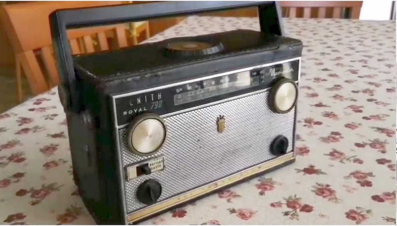
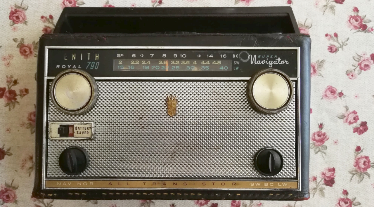
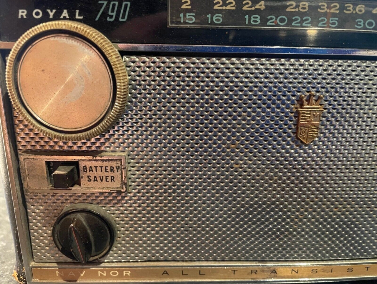
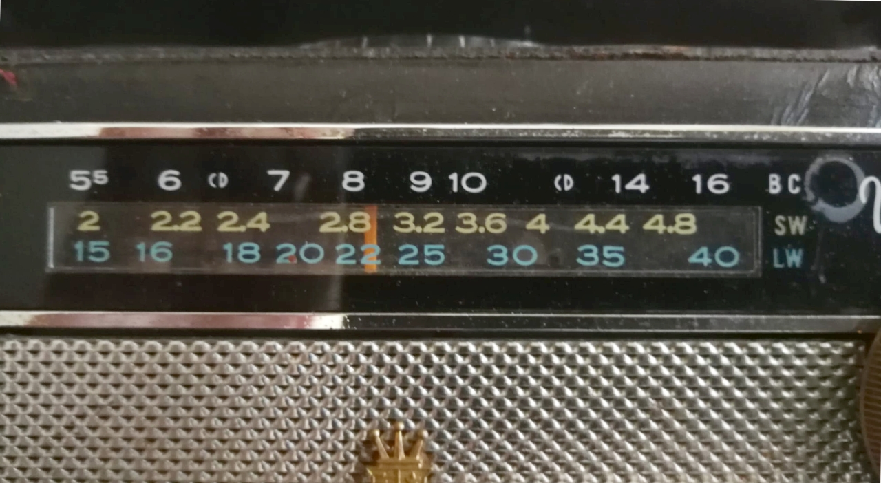
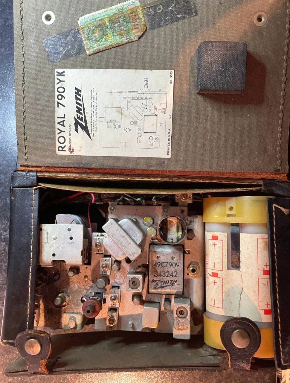
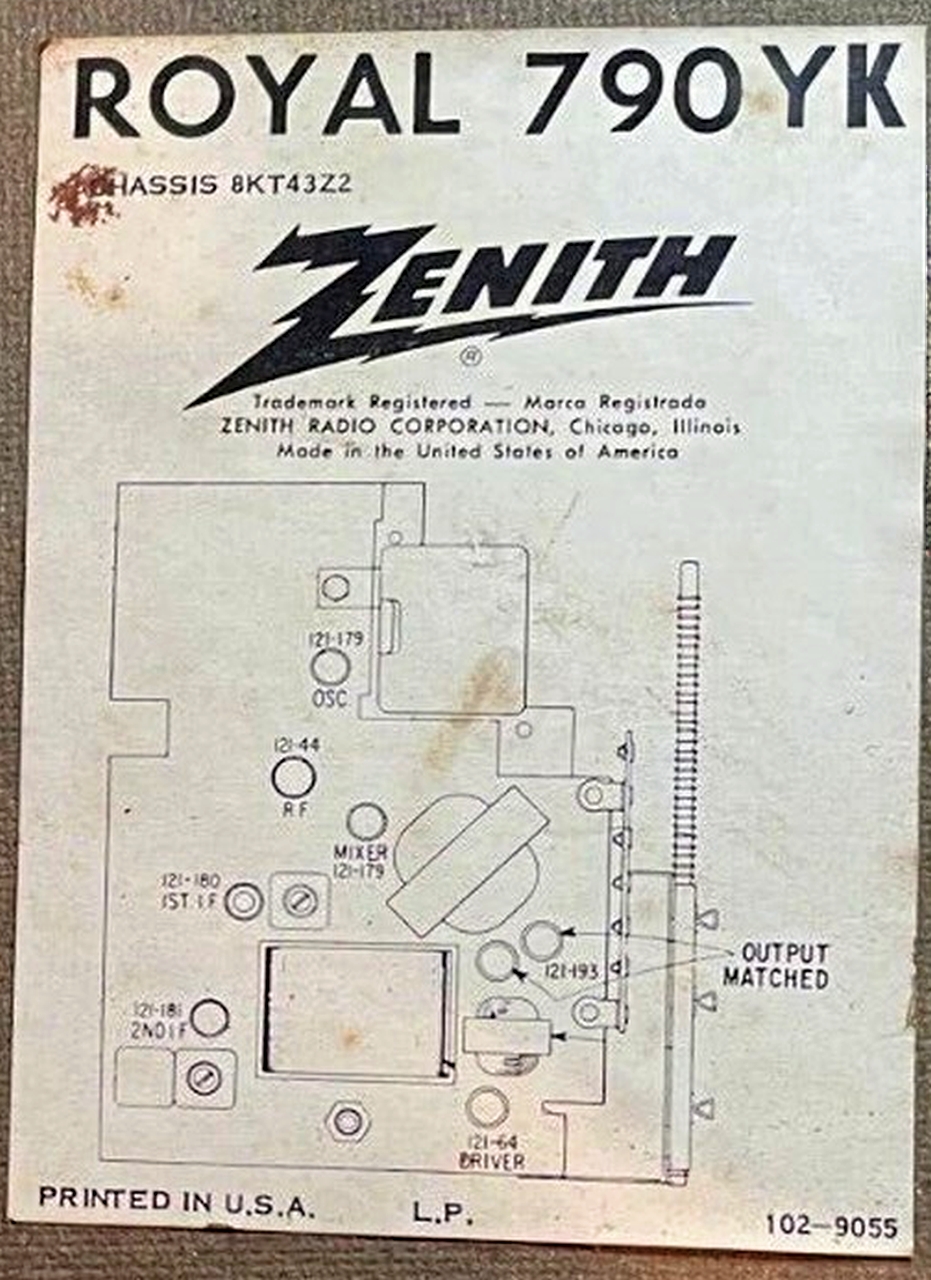
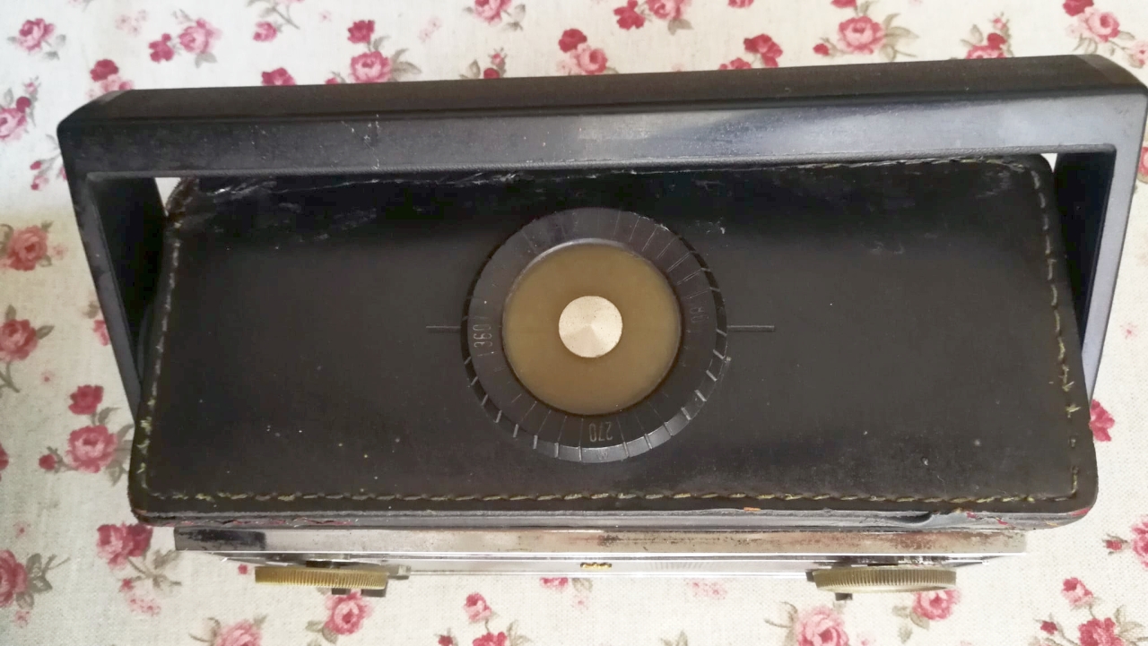
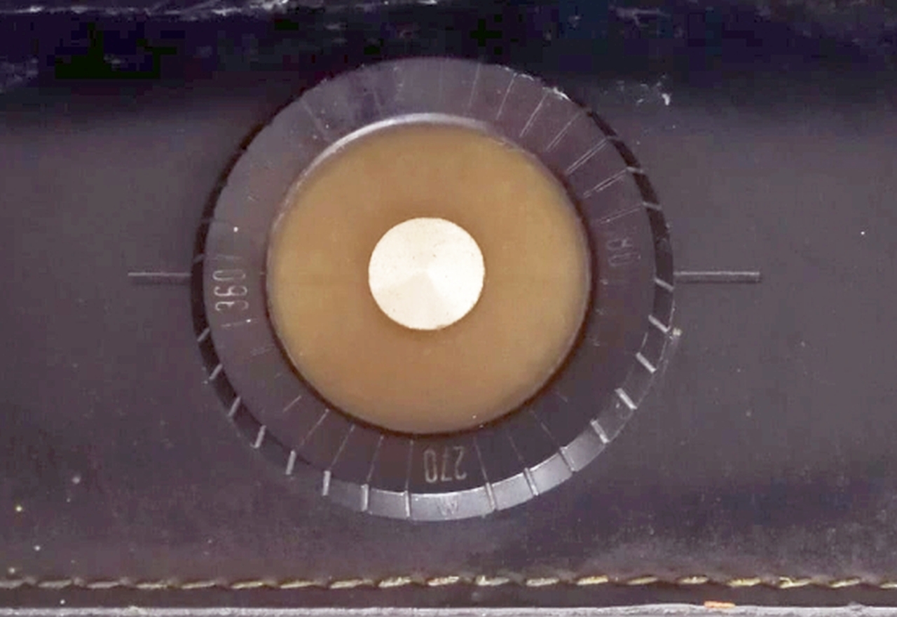
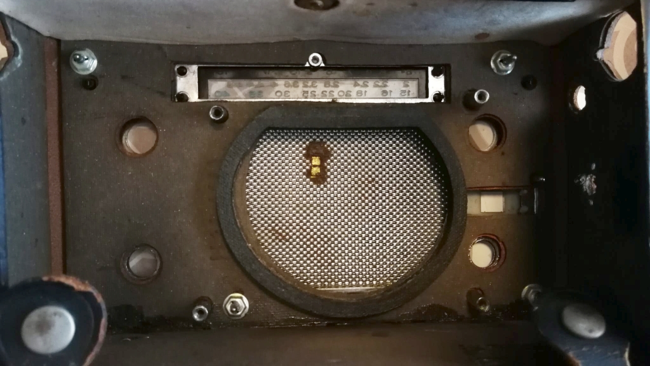
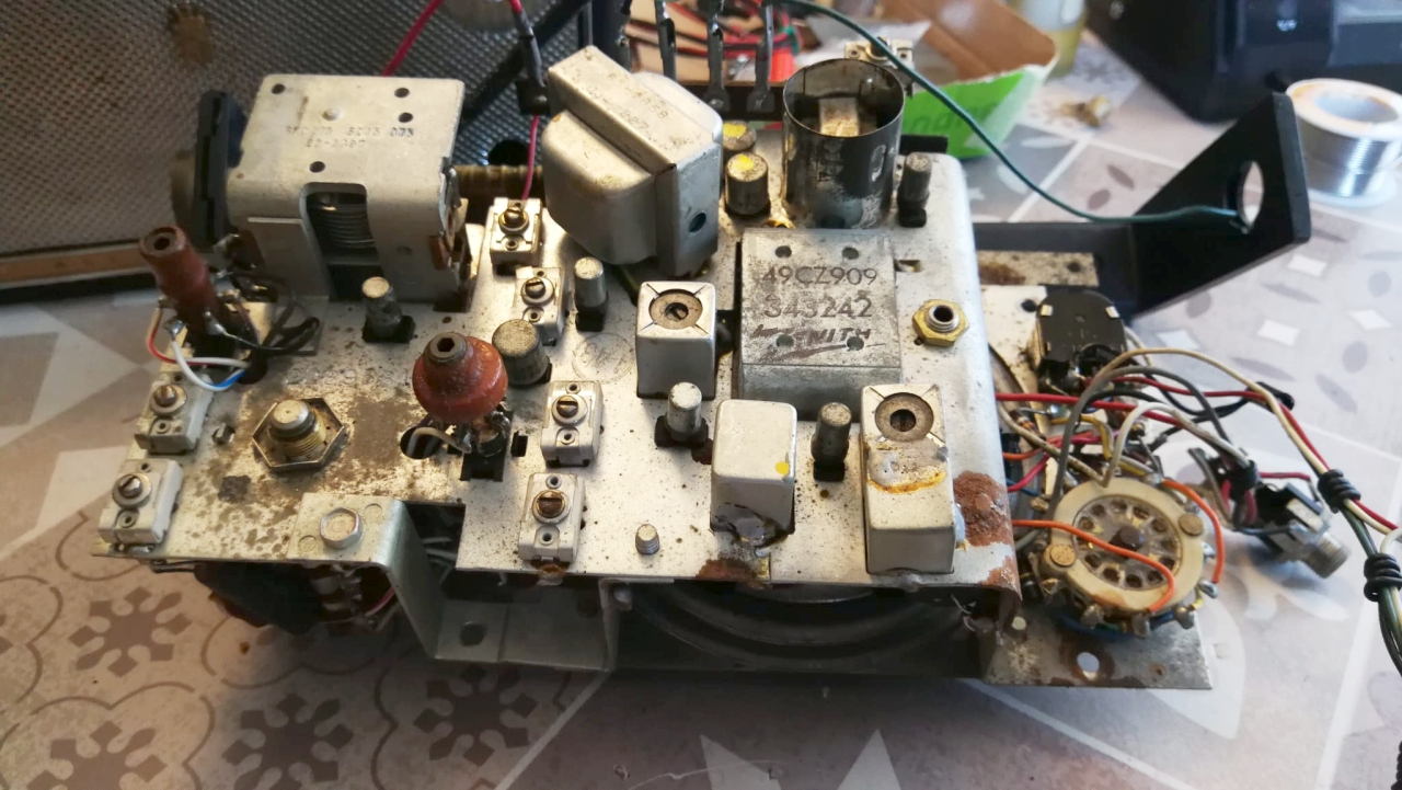
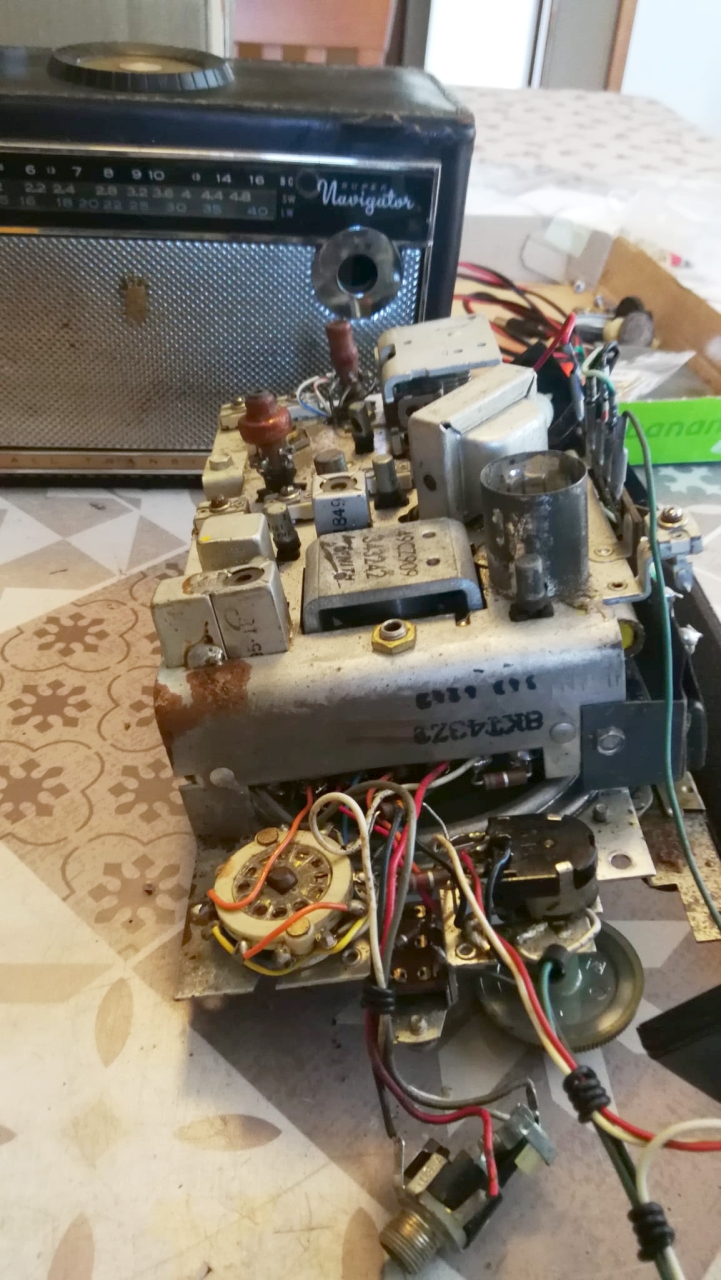
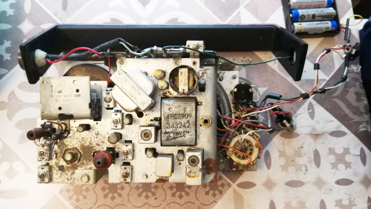
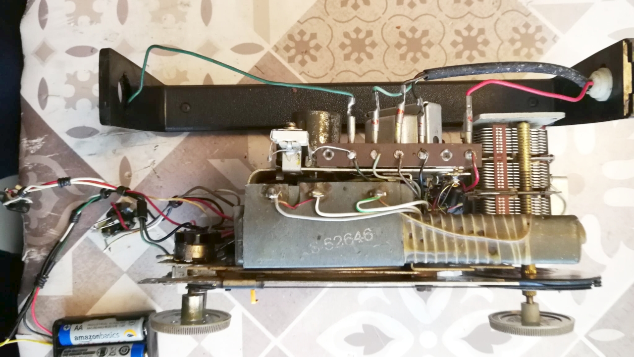
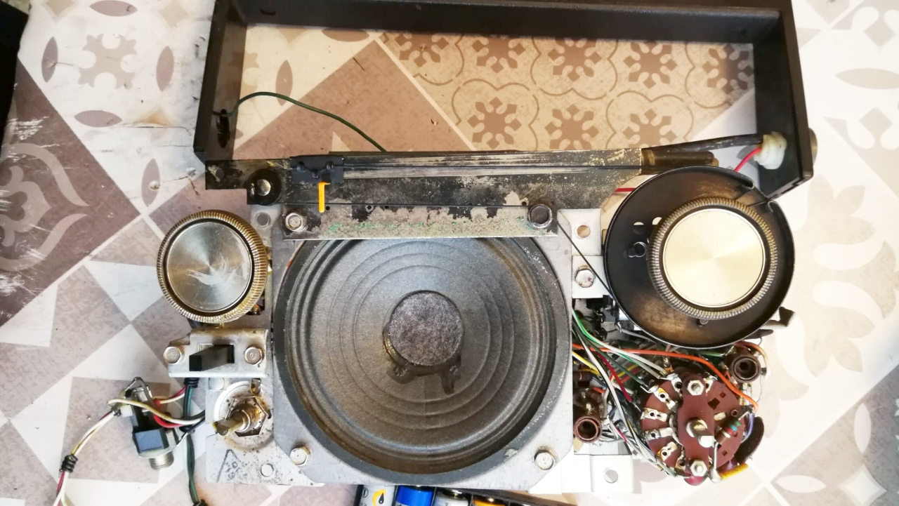
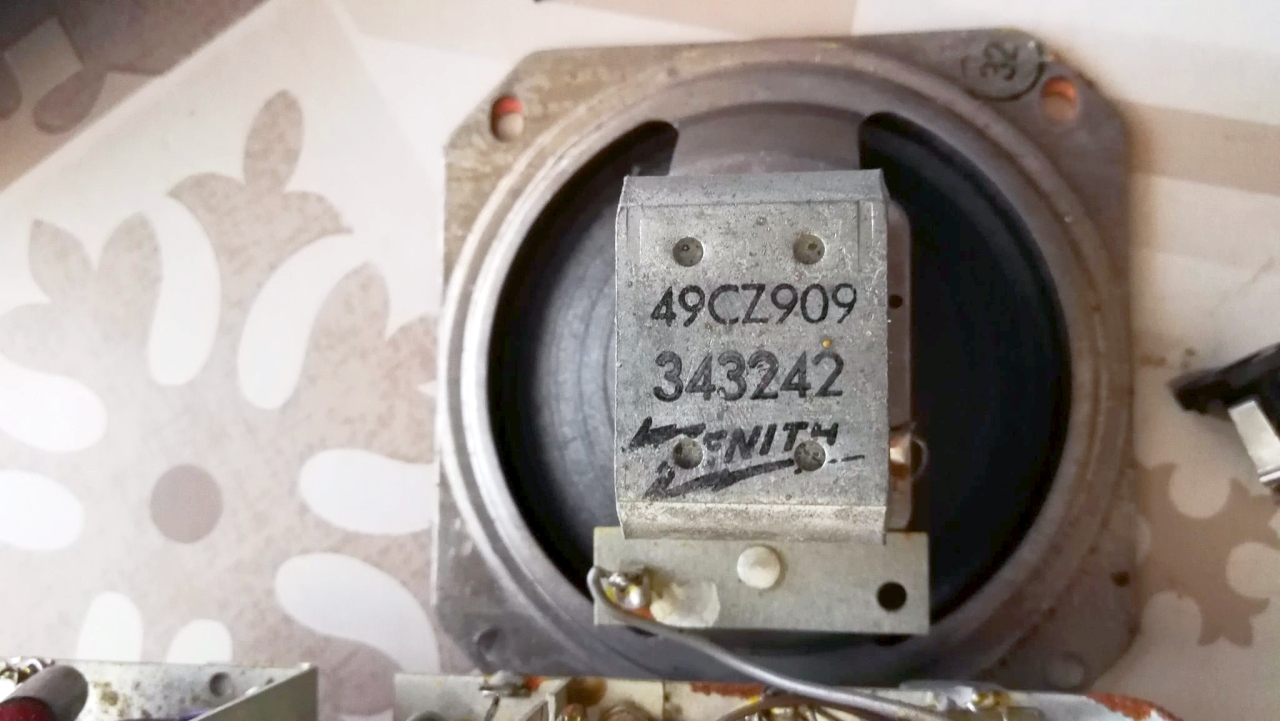
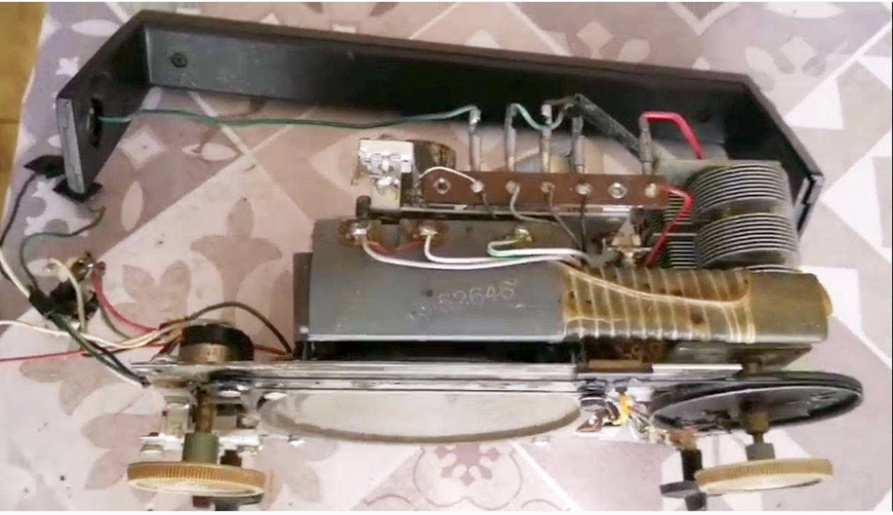
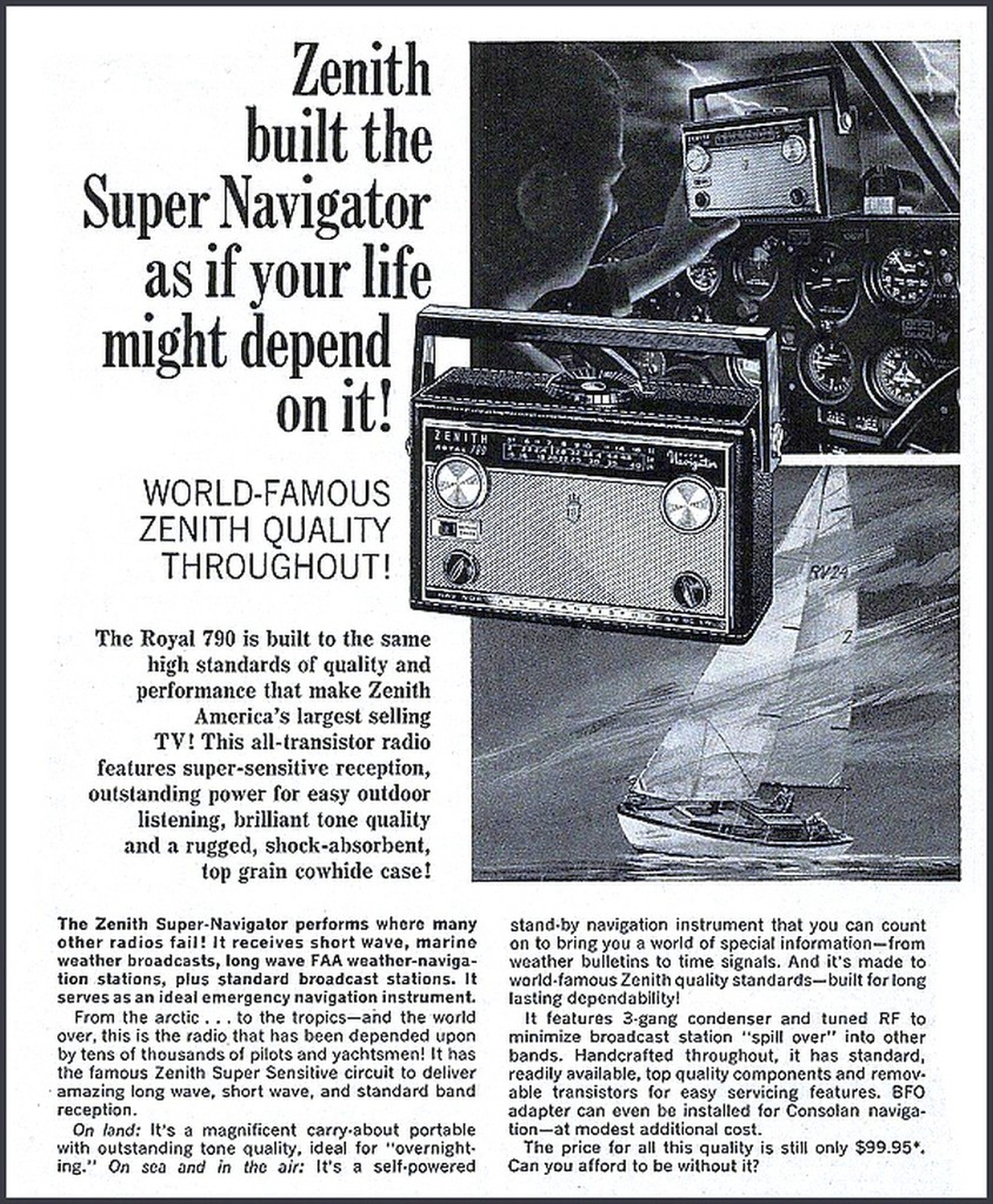
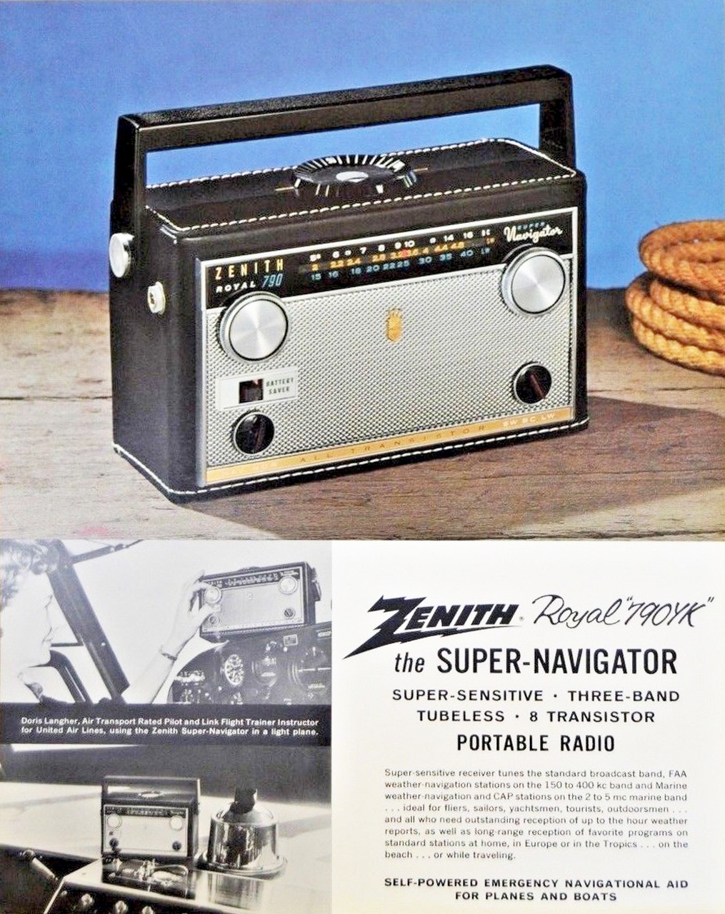
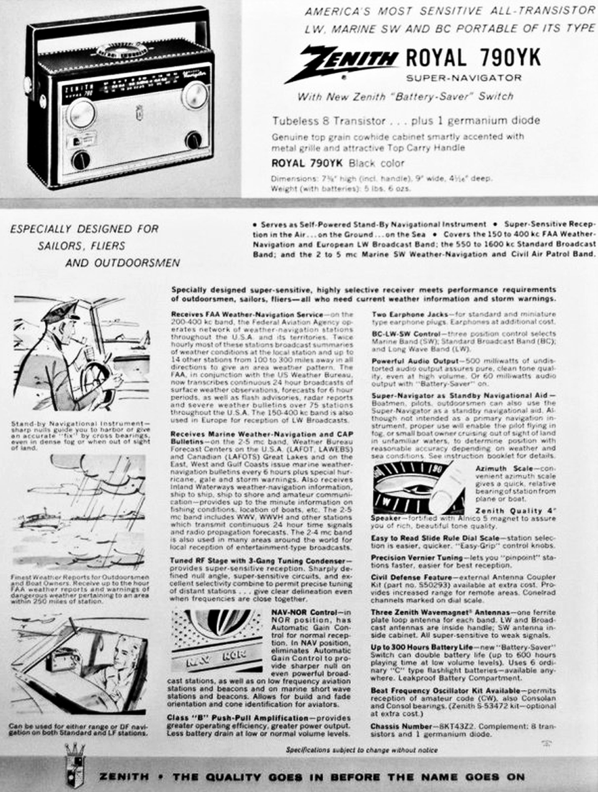
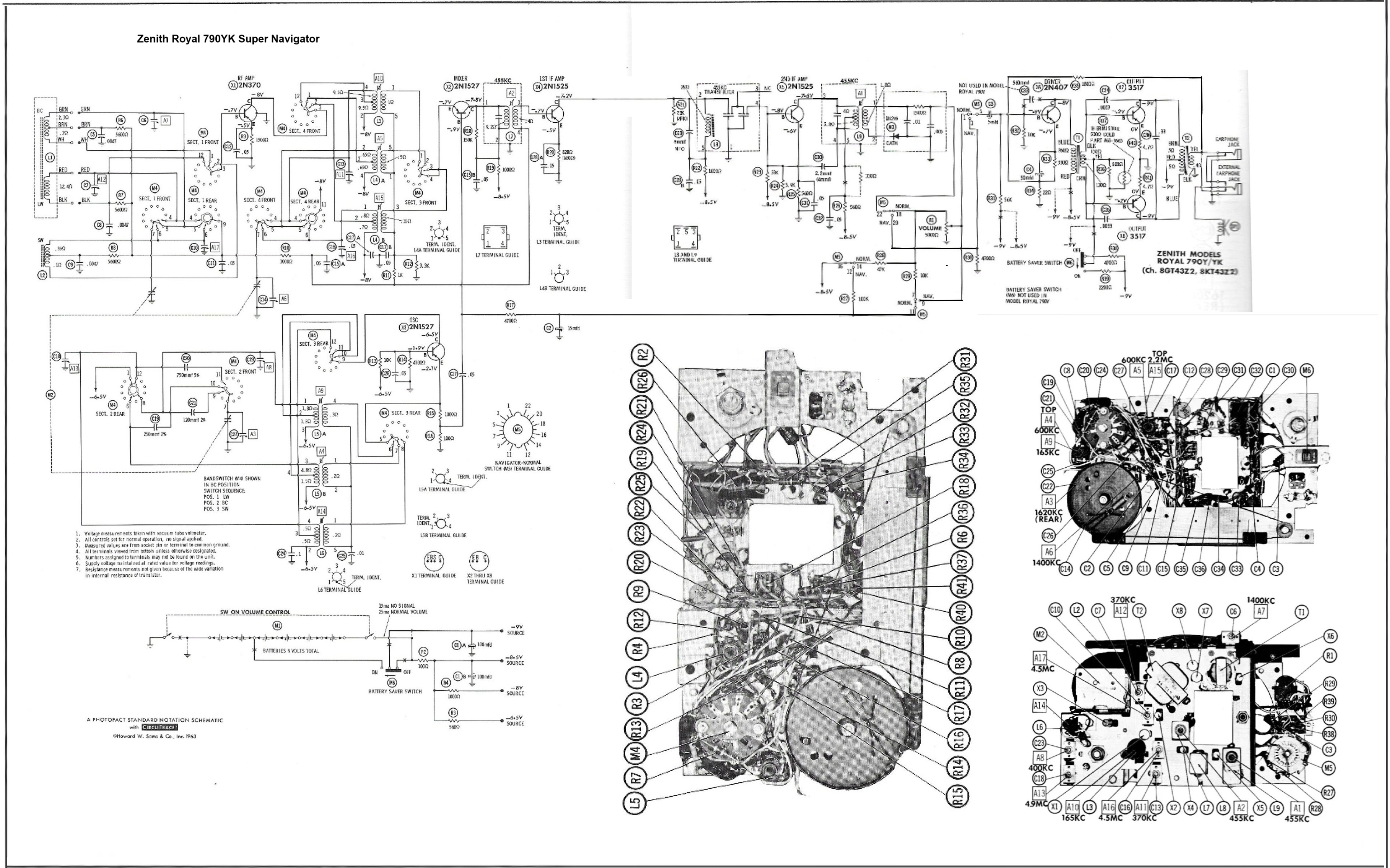
Zenith Navigators were receivers specifically designed for use as direction finders by aviators and recreational sailors. All Navigators, when pointed in the direction of a known radio station, allowed users to navigate to a landing place or airport even at night or in poor visibility. The 790YK model in particular was equipped with a switch that could override the AGC (Automatic Gain Control) circuit, making it extremely sensitive. The circuit was a superheterodyne using eight PNP germanium transistors, which were easily replaceable in the event of a fault because they were inserted into special Bakelite sockets: 121-44, 121-179, 121-179, 121-180, 121-181, 121-64, 121-193, 121-193. Reception was possible on three wavebands: Long Wave, Medium Wave and Short Wave. The circuit included a radio frequency amplifier (124-44), the local oscillator (121-179), the mixer (121-179), the first IF amplifier at 455 kHz (121-180), the second IF amplifier at 455 kHz (121-181), the audio preamplifier (121-64), the driver transistor (121-64), and the pair of class "B" push-pull power transistors of the audio output stage (2 x 121-193). The tuning capacitor had three air-insulated sections and presumably displayed the component's manufacturing date: 6245, or the 45th week of 1962 (November 3-9). The radio's controls were located on the front panel, from left to right and top to bottom: power switch/volume, tuning, battery saver, AGC on/off, band shifter: SW, BC, LW. On the top of the radio was a rotating graduated dial; this dial could be used to mark the direction of North and to sight the displacement in degrees that needed to be made to reach the transmitting station and the destination. There were two antennas: the L1 antenna for Medium and Long Waves was wound on a long ferrite core inserted into the carrying handle, while the L2 antenna for Short Waves was another ferrite core attached to the top of the chassis. The tuning dial was located on the top of the front panel, above the aluminum grille protecting the speaker. The cabinet was constructed of various materials: wood-pressed cardboard, plastic, and leather.The speaker was a magnetodynamic one with a diameter of 4 inches. On the left side of the cabinet there was a headphone jack. The power supply used a 9-volt voltage supplied by six 1.5V type C (R14) batteries. A socket after the second battery supplied the circuit with 3V, which powered the radio when the "Battery Saver" switch was activated. Although the performance was very limited, this greatly extended battery life. The speaker was a 4-inch (10.2 cm) magnetodynamic type, and the radio's dimensions were 9.842 x 5.9 x 4.33 in, weighing 5.07 lb. © IK3HIA 2024. |
||||||
 |
 |
 |
 |
|||
|
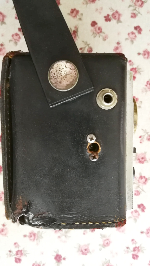
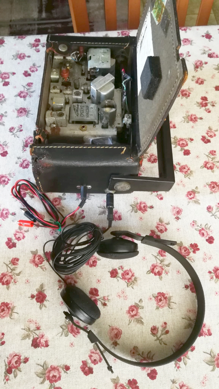
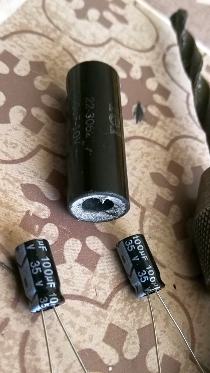
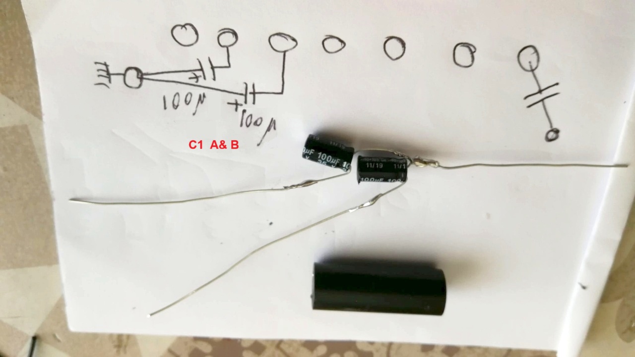
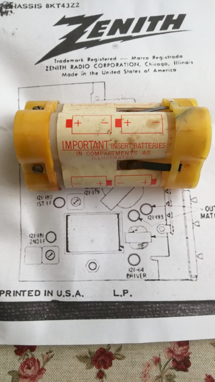
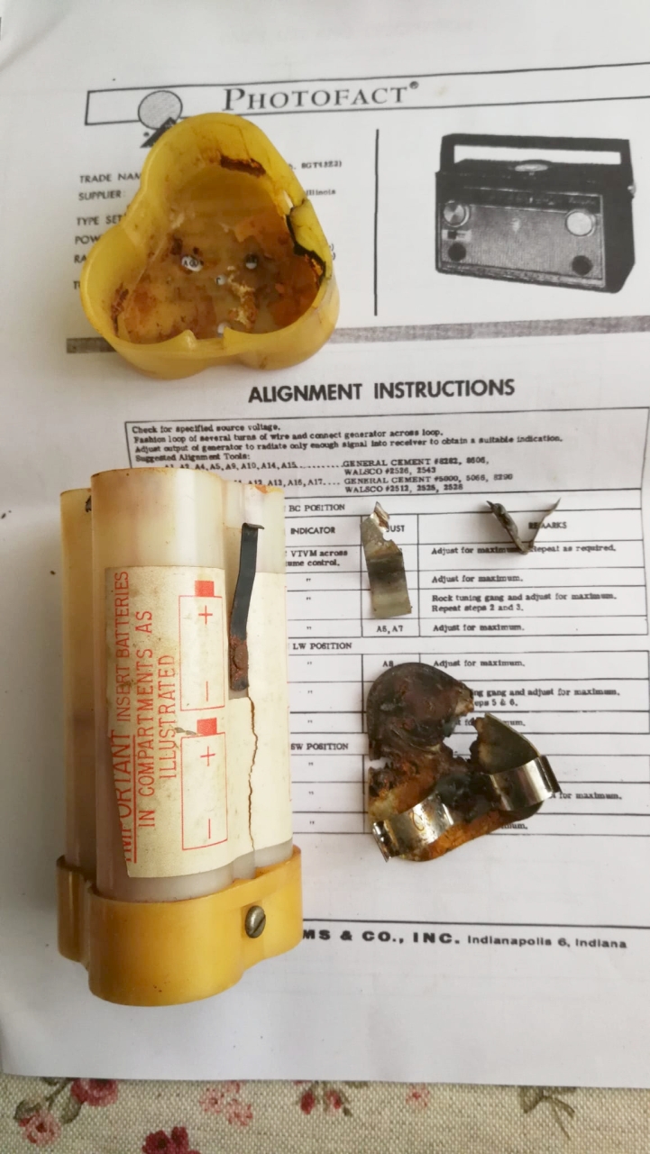
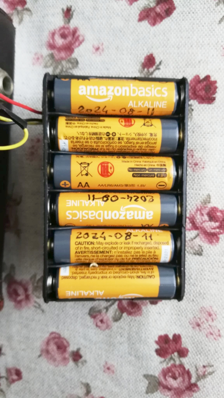
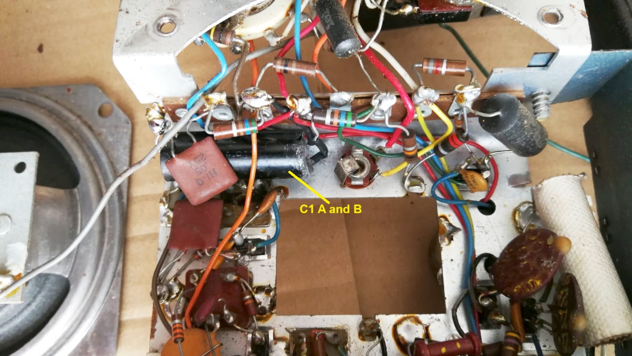
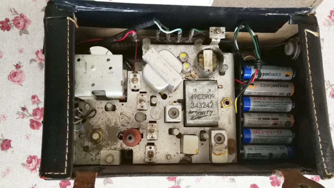
To restore the Zenith Royal 790YK to working order, I had to replace the original plastic battery case, whose contacts were destroyed by acid from someone leaving dead batteries inside for a long time. The leaking acid had also damaged the rear left corner of the cabinet. To replace the battery case, I used a modern one for six AA cells in which, after the second 1.5 cell, I soldered the 3 V wire for "Battery Saver" mode. The second step was to replace all the electrolytic capacitors: C1 (A and B), C2, C3, and C4. For C1 I preferred to keep the original casing and, after drilling an appropriate hole, I insert the 2 new components. Third step, since all the transistors were socketed, I was able to remove them and check them one by one with a transistor tester. The last step was to use deoxidizing spray on the potentiometer, band selector, and switches. To get the spray onto the potentiometer switch contacts, I carefully drilled a small hole in the plastic using a 1.5mm drill bit, which I then covered with a small piece of black electrical tape. A previous owner had installed a convenient 9V DC external power socket on the left side of the radio. After carefully checking the connections, I successfully used it to power the radio and verify its excellent operation. The receiver proved to be very sensitive and capable of receiving the rare stations still present on medium waves in broad daylight. © IK3HIA 2024. |
||||||
|
|
||||||
 |
 |
 |
 |
|||
 |
 |
 |
 |
|||
|
Gli Zenith Navigator erano ricevitori progettati appositamente per essere utilizzati come un radiogoniometri da aviatori o marinai da diporto. Tutte le Navigator se venivano orientate nella direzione di una stazione radio nota, permettevano agli utilizzatori di dirigersi verso un approdo o un aeroporto anche di notte o in caso di scarsa visibilità. Il modello 790YK in particolare era dotato di un interruttore che poteva escludere il circuito AGC (Controllo Automatico di Guadagno) e renderla estremamente sensibile. Il circuito della Super Navigator era una supereterodina che utilizzava otto transistor PNP al germanio che tra l'altro erano facilmente sostituibili in caso di guasto perchè erano inseriti in speciali zoccoli di bachelite: 121-44, 121-179, 121-179, 121-180, 121-181, 121-64, 121-193, 121-193. La ricezione era possibile in tre gamme d'onda: Onde Lunghe, Onde Medie e Onde Corte. Il circuito comprendeva un amplificatore a Radio frequenza (124-44), l'Oscillatore Locale (121-179), il mixer (121-179), il primo amplificatore di Frequenza Intermedia a 455 kHz (121-180), la seconda Frequenza Intermedia a 455 kHz (121-181), il preamplificatore audio (121-64), il transistor pilota (121-64) e la coppia di transistor di potenza in Push-Pull classe "B" dello stadio finale audio (2 x 121-193). Il condensatore di sintonia disponeva di tre sezioni con isolamento ad aria e presumibilmente mostrava la data di costruzione del componente: 6245, ovvero la 45a settimana del 1962 (3-9 novembre). I comandi della radio erano situati sul pannello frontale, da sinistra a destra e dall'alto in basso: interruttore di accensione-volume, sintonia, risparmio batteria, AGC on/off, cambio gamma: OC, OM, OL. Sul lato superiore della radio era situata una ghiera graduata girevole, su questo nonio si poteva riportare la direzione del Nord e traguardare lo spostamento in gradi che bisognava effettuare per raggiungere la stazione emittente e a ldestinazione. Le antenne erano due: la L1 per le Onde Medie e Lunghe era avvolta su un lungo nucleo di ferrite inserito nella maniglia per il trasporto, l'antenna L2 per le Onde Corte era un altro nucleo di ferrite fissato sulla parte superiore dello chassis. La scala di sintonia era situata sulla parte superiore del pannello frontale, sopra la griglia di alluminio che proteggeva l'altoparlante. Il mobiletto era costruito con materiali vari: legno-cartone pressato, plastica e pelle. L'altoparlante era magnetodinamico con il diametro di 4 inch = 10.2 cm. Sul lato sinistro del mobile era presente una presa per le cuffie. L'alimentazione utilizzava una tensione di 9 Volt fornita da 6 batterie da 1,5V tipo C (R14), una presa dopo la seconda batteria forniva al circuito 3 V che alimentavano la radio quando veniva azionato l'interruttore "Battery Saver" e anche se con prestazioni molto limitate in tal modo l'autonomia veniva prolungata di molto. L'altoparlante era un magnetodinamico con diametro di 4 inch / 10.2 cm e le dimensioni della radio erano: 25 x 15 x 11 cm, e il peso era di 2300 g. © IK3HIA 2024. |
||||||
 |
 |
 |
 |
|||
 |
 |
 |
 |
|||
|
Per ripristinare il funzionamento della Zenith Royal 790YK ho dovuto sostituire il contenitore batterie originale in plastica che aveva i contatti distrutti dall'acido perché qualcuno aveva lasciato per molto tempo le batterie esaurite all'interno. La fuoriuscita dell'acido aveva inoltre rovinato l'angolo posteriore sinistro del mobiletto. Per la sostituzione del portabatterie ne ho usato uno moderno per sei elementi AA in cui ho ricavato anche la presa a 3 V dopo la seconda pila per il funzionamento in modalità "Battery Saver". La seconda operazione è stata la sostituzione dei condensatori elettrolitici C1 (A e B), C2, C3 e C4. Per il C1 ho preferito conservare l'involucro originale e, dopo opportuna foratura, inserire all'interno i componenti nuovi. Terza operazione, essendo tutti i transistor montati su zoccolo ho potuto estrarli e controllarli ad uno ad uno con un provatransistori. L'ultimo intervento è stato di usare lo spray disossidante sul potenziometro, sul commutatore di banda e sugli interruttori. Per riuscire a far arrivare lo spray sui contatti dell'interruttore del potenziometro ho praticato con cautela sulla plastica un forellino usando una punta da trapano da 1,5 mm che poi ho coperto con un pezzettino di nastro isolante nero. Un precedente proprietario aveva ricavato sulla fiancata sinistra della radio una comoda presa per l'alimentazione esterna a 9 Vcc che, dopo averne opportunamente verificato i collegamenti, ho potuto utilizzare con successo per alimentare la radio e verificarne l'ottimo funzionamento. Il ricevitore infatti ha dimostrato di essere molto sensibile e di poter ricevere in pieno giorno le rare stazioni ancora presenti oggi sulle Onde Medie.
© IK3HIA 2024.
|
||||||
|
||||||
 |
 |
 |
 |
|||
 |
 |
 |
 |
|||
|
Return to top of
page
|
||||||
| Back to: |
|
IK3HIA home page |
|
Zenith Radio page |
|
Transistor Radio page |
|
Transistor diagrams |