 |
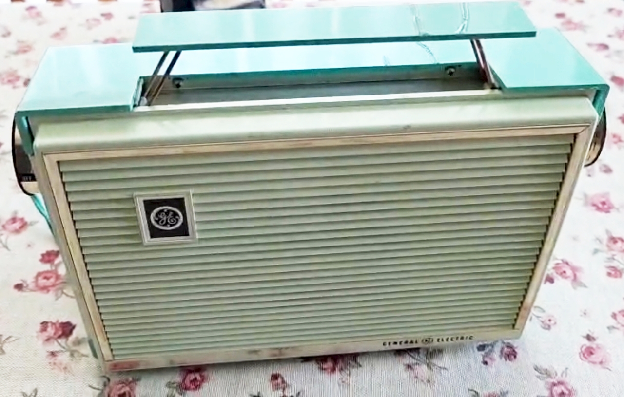
General Electric
P-673 -
U.S.A. 1956 * Restoration * |
|
|
|
General Electric
P-673 -
U.S.A. 1956 * Restoration * |
|
|
|
 |
Restauro
|
|||||
|
|
|||||||
 |
 |
 |
 |
||||
|
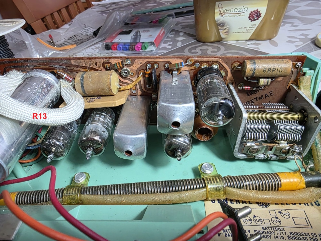
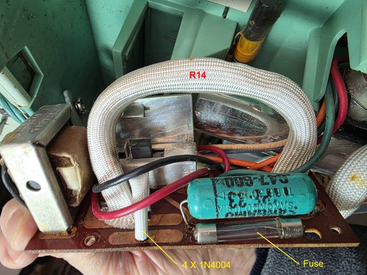
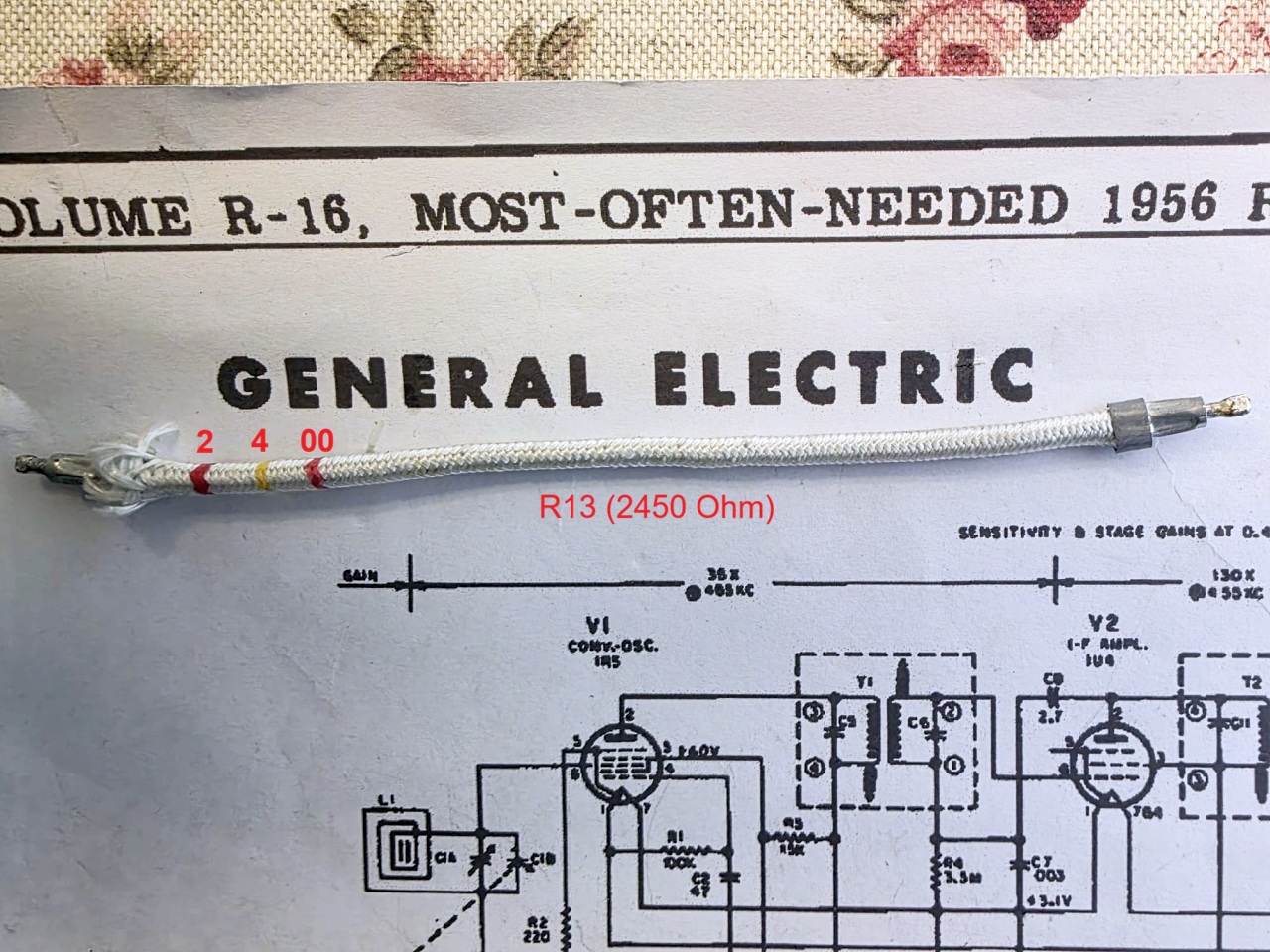
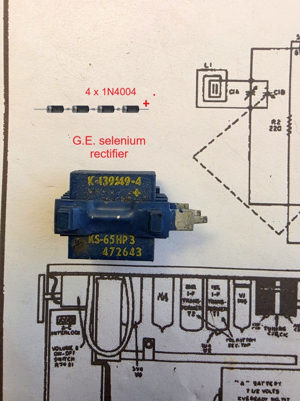
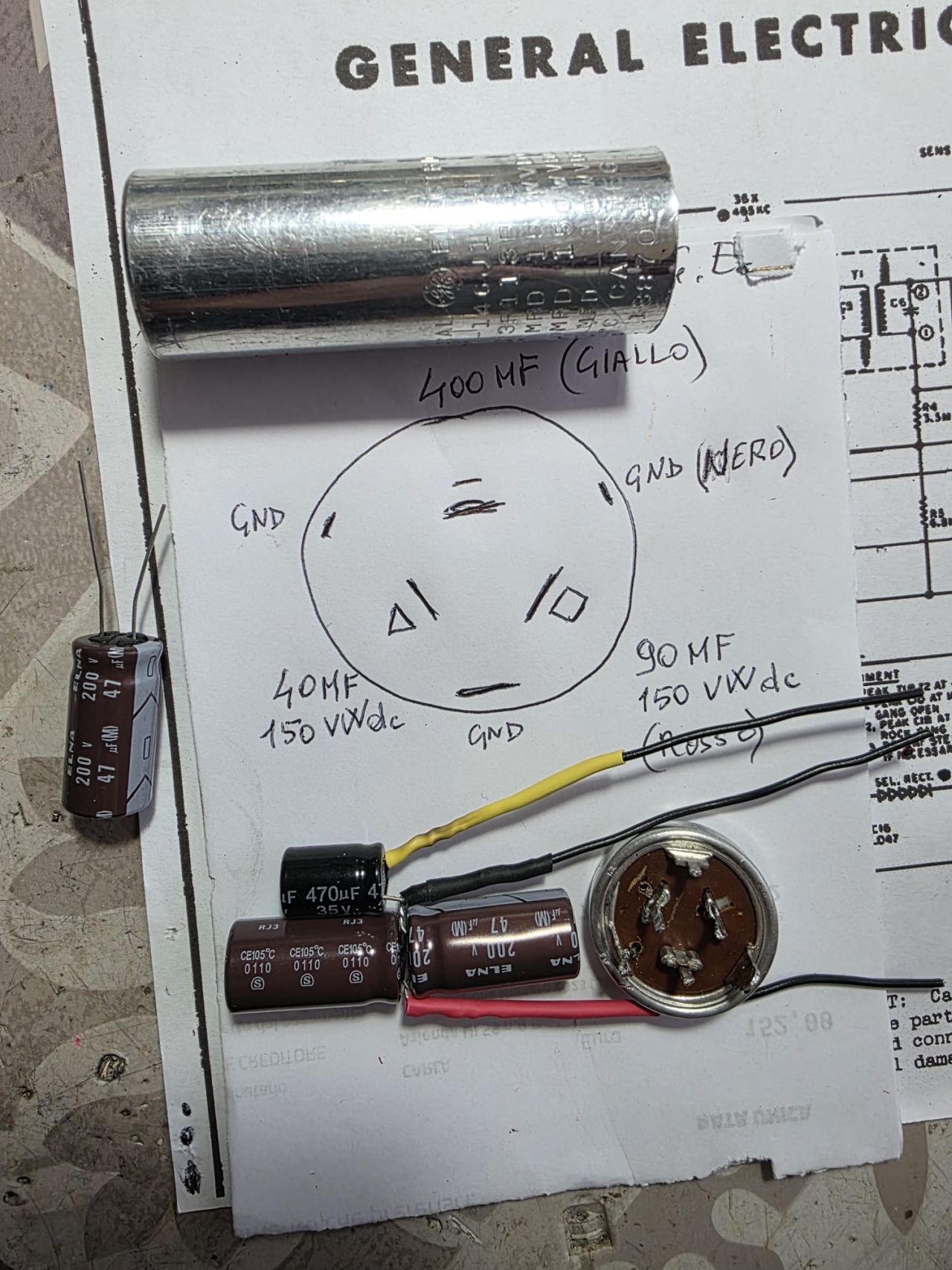
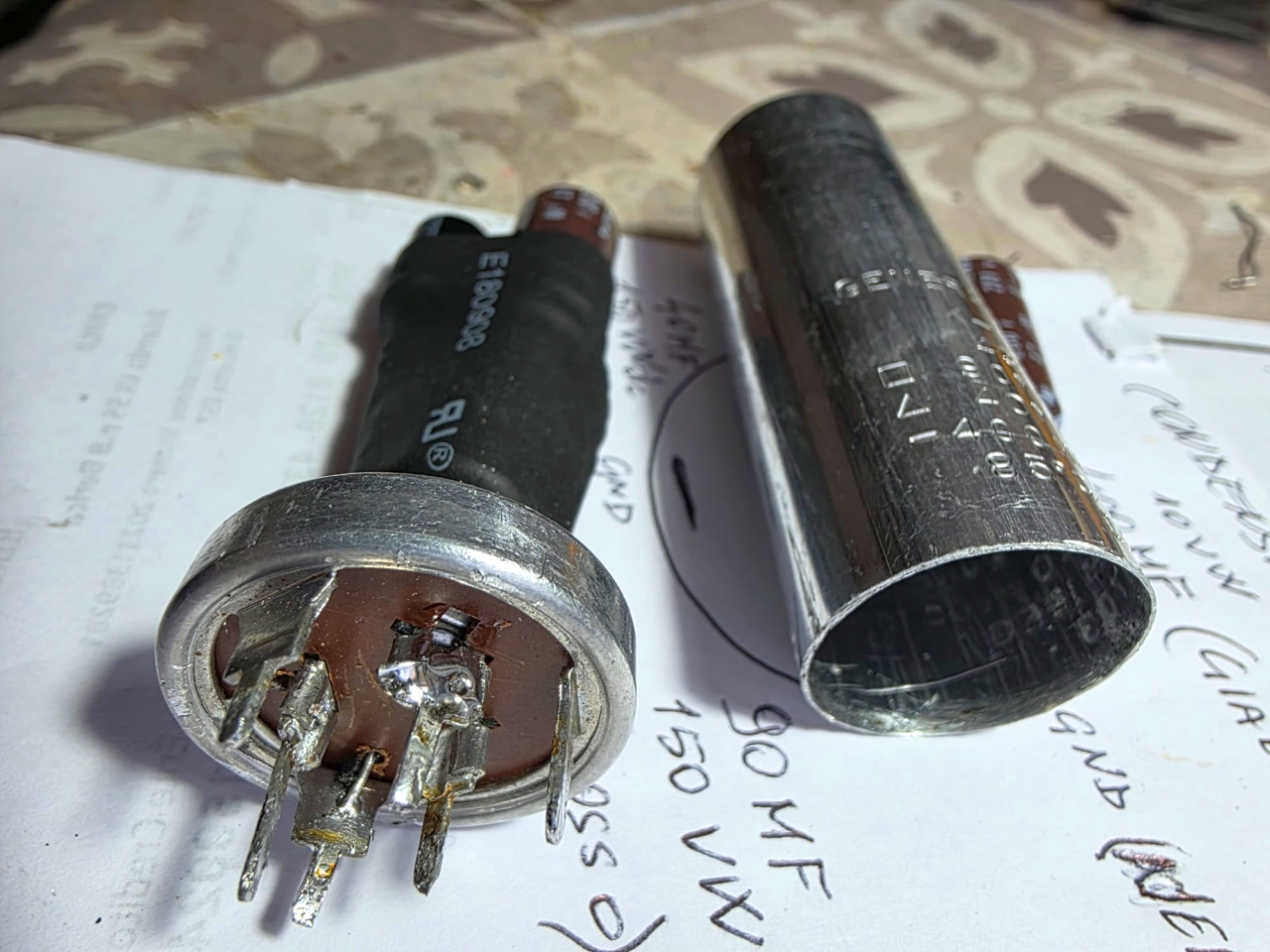
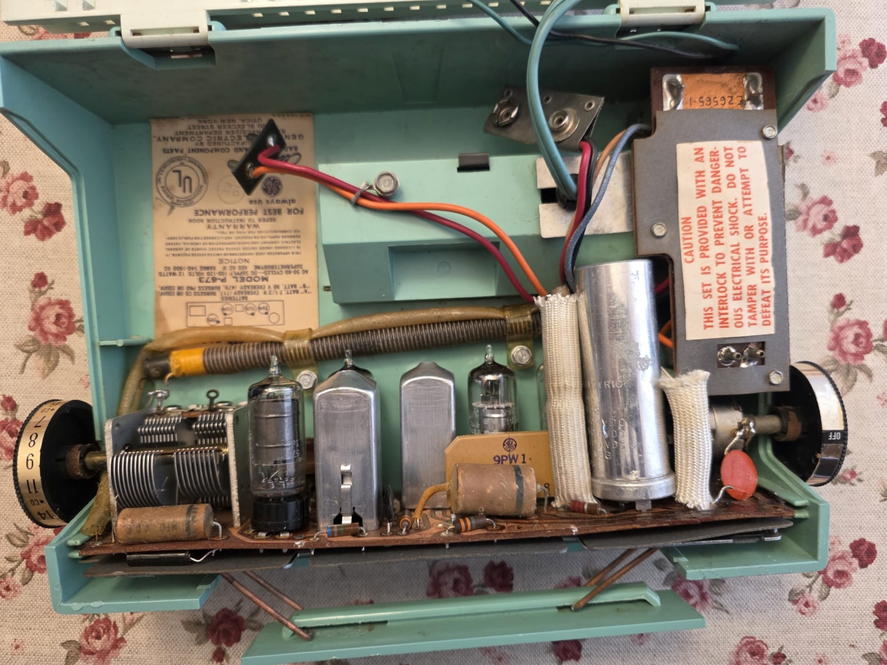
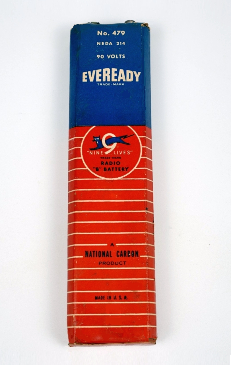
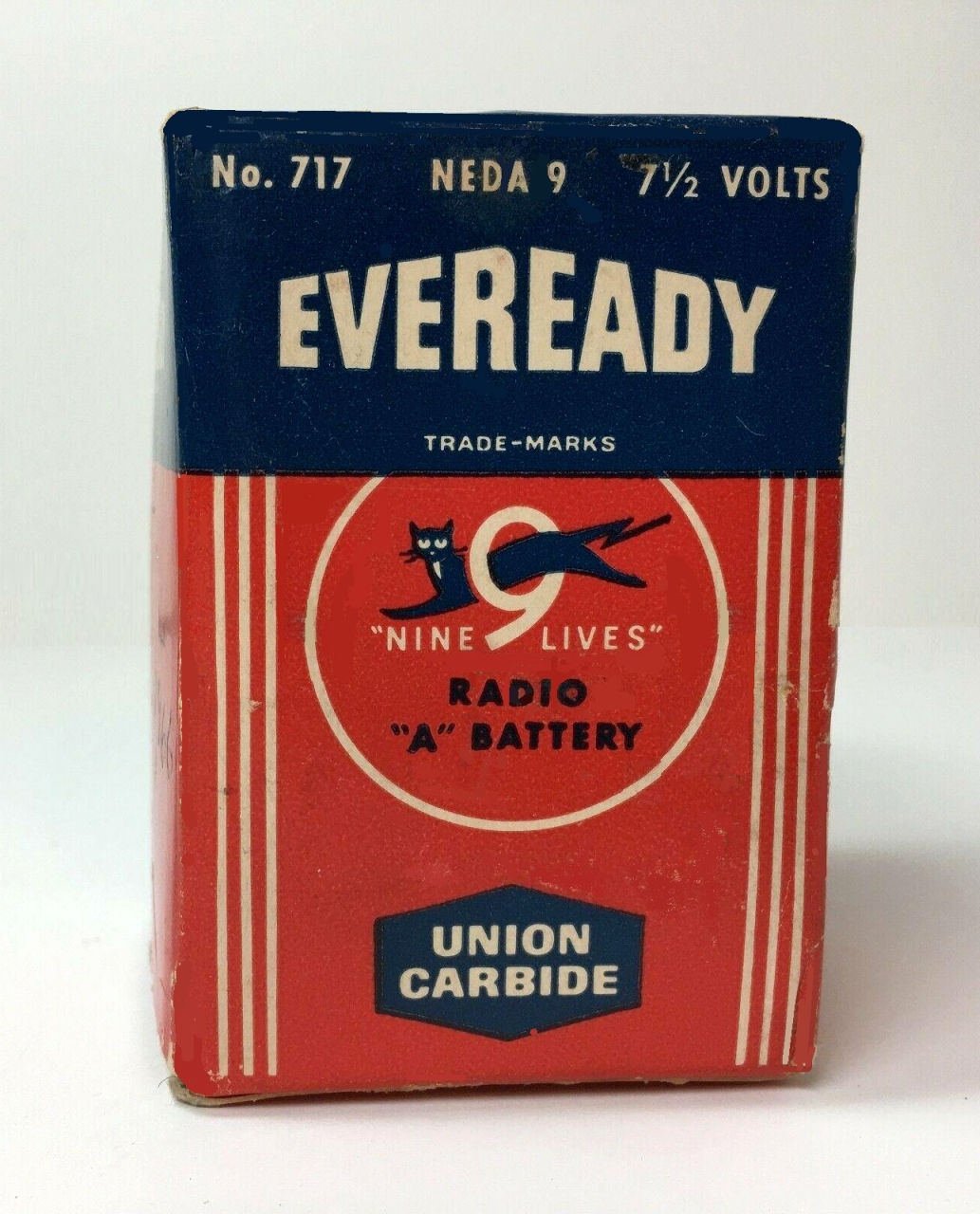
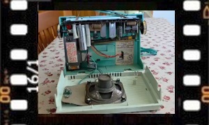
Dopo aver aperto la radio, rimosso le viti, le coperture in cartoncino e liberati i due circuiti stampati, ho trovato il fusibile presente nella schedina di alimentazione bruciato. Probabilmente un precedente proprietario aveva collegato la radio alla tensione 220 Vac europea anziché alla 110 Vac utilizzata negli USA. Fortunatamente il fusibile non ha obbedito alla legge di Murphy, i filamenti delle valvole non si sono bruciati così ho potuto proseguire con il restauro della radio sostituendo il fusibile interrotto con uno da 6,3 × 32 mm e 400 mA. Sempre sulla scheda di alimentazione ho deciso di sostituire preventivamente l'ancora efficiente ma potenzialmente pericoloso raddrizzatore al selenio (link all'interessante spiegazione di enrylab). Come nuovo raddrizzatore ho utilizzato 4 diodi al silicio 1N4004 collegati in serie in modo da ottenere all'incirca la stessa resistenza e quindi la stessa caduta di tensione che presentava il vecchio raddrizzatore originale. Sempre preventivamente ho sostituito tutti i condensatori elettrolitici della radio con altri nuovi dello stesso valore ma con superiori tensioni di lavoro. Ho utilizzato il vecchio contenitore di alluminio dell'originale condensatore multiplo, segandolo alla base con il seghetto da traforo, svuotandolo pazientemente del contenuto e ripulendo i residui con carta da cucina e alcool denaturato. I condensatori elettrolitici moderni sono piccoli e sono riuscito a stipane alcuni nel vecchio contenitore di alluminio in modo da ottenere le capacità necessarie. Prima di dare tensione (110Vac tramite autotrasformatore), controllando la continuità dei collegamenti ho trovato interrotta la grossa resistenza a filo R13 che è utilizzata per l'alimentazione dei filamenti delle valvole. Sullo schema R13 risulta da 2450 Ohm 10 W e per ripristinarla ho utilizzato 3 resistenze da 820 Ohm 10 % da 5 W saldate in serie e nascoste con spezzoni della vecchia guaina isolante (tessuto in fibra di vetro?) della resistenza a filo originale. Una volta saldata la nuova resistenza R13 ho verificato le tensioni fornite dall'alimentatore che risultavano 85 V misurati sul piedino 3 della V4 e 6,8 V misurati sul piedino 7. Le tensioni erano più basse del dovuto, ma questo mi andava bene in quanto avrebbero garantito il funzionamento sollecitando meno le valvole. (Continua »). |
|||||||
 |
 |
 |
 |
||||
|
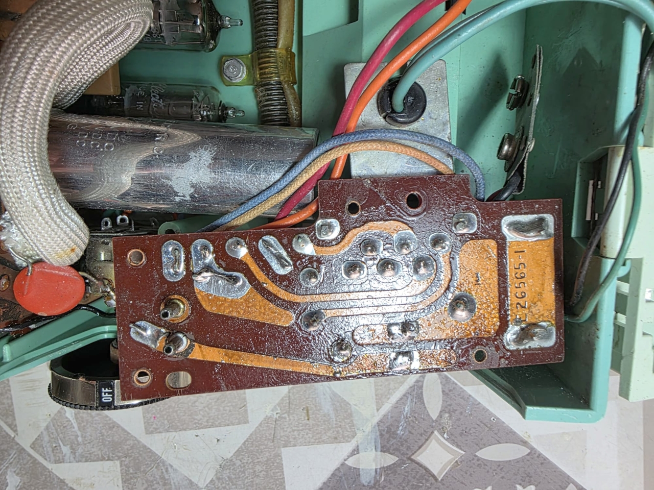
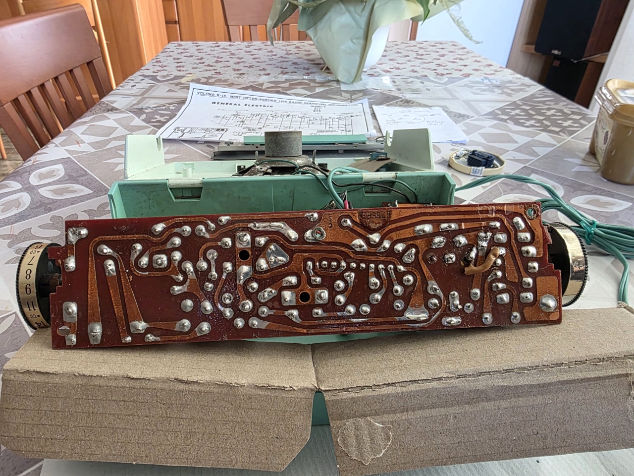
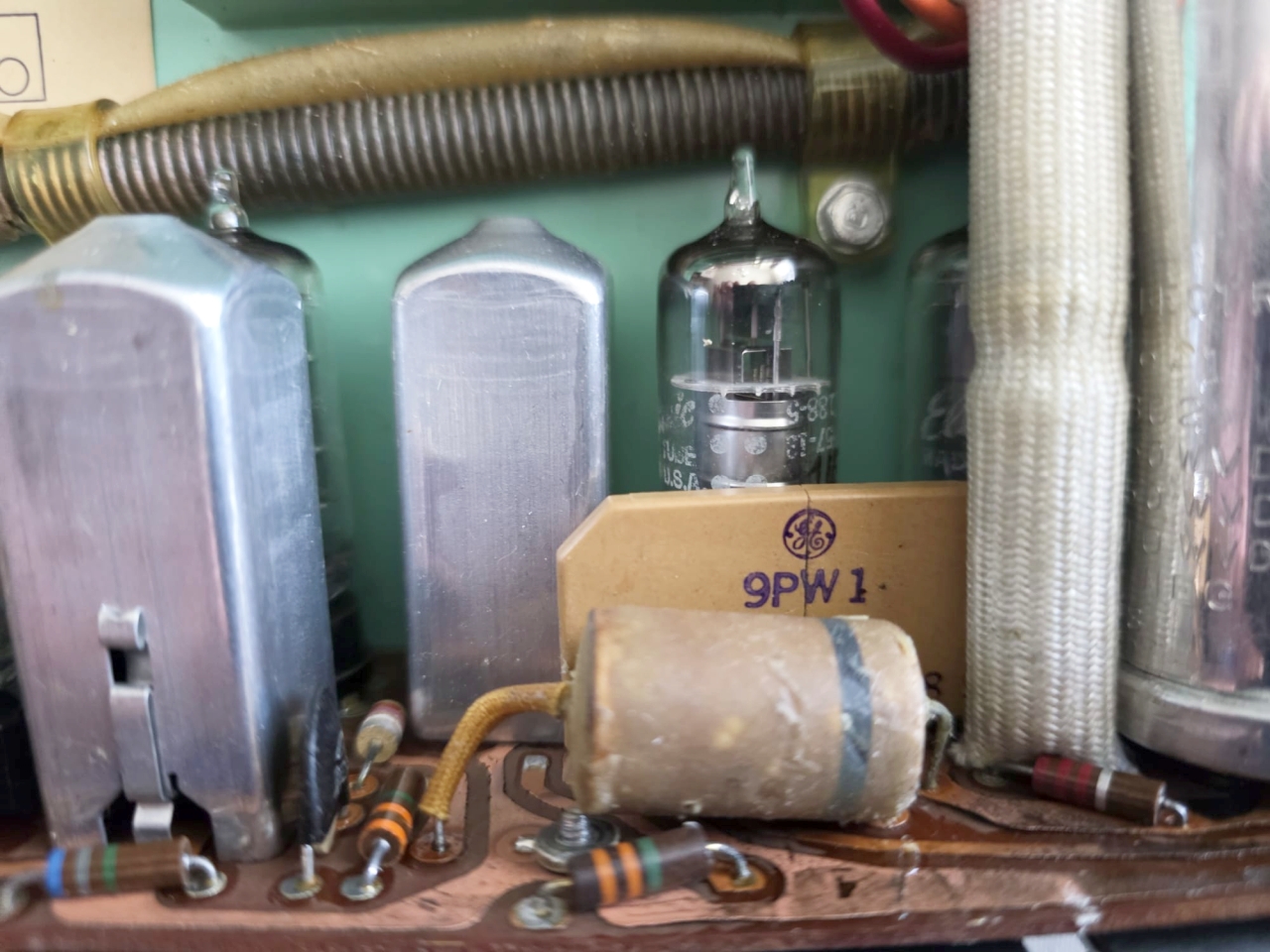
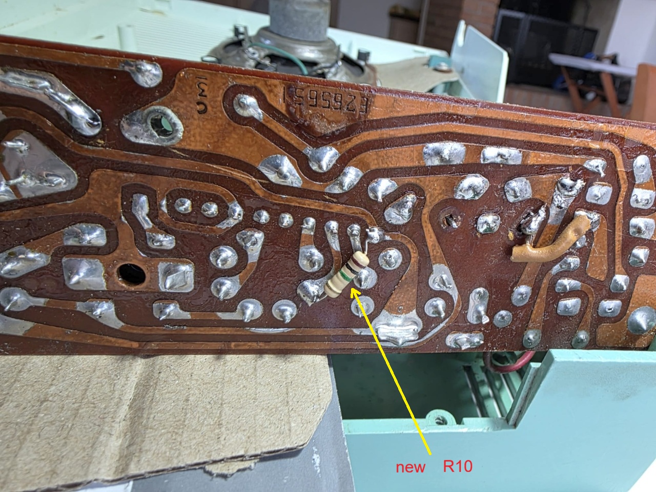
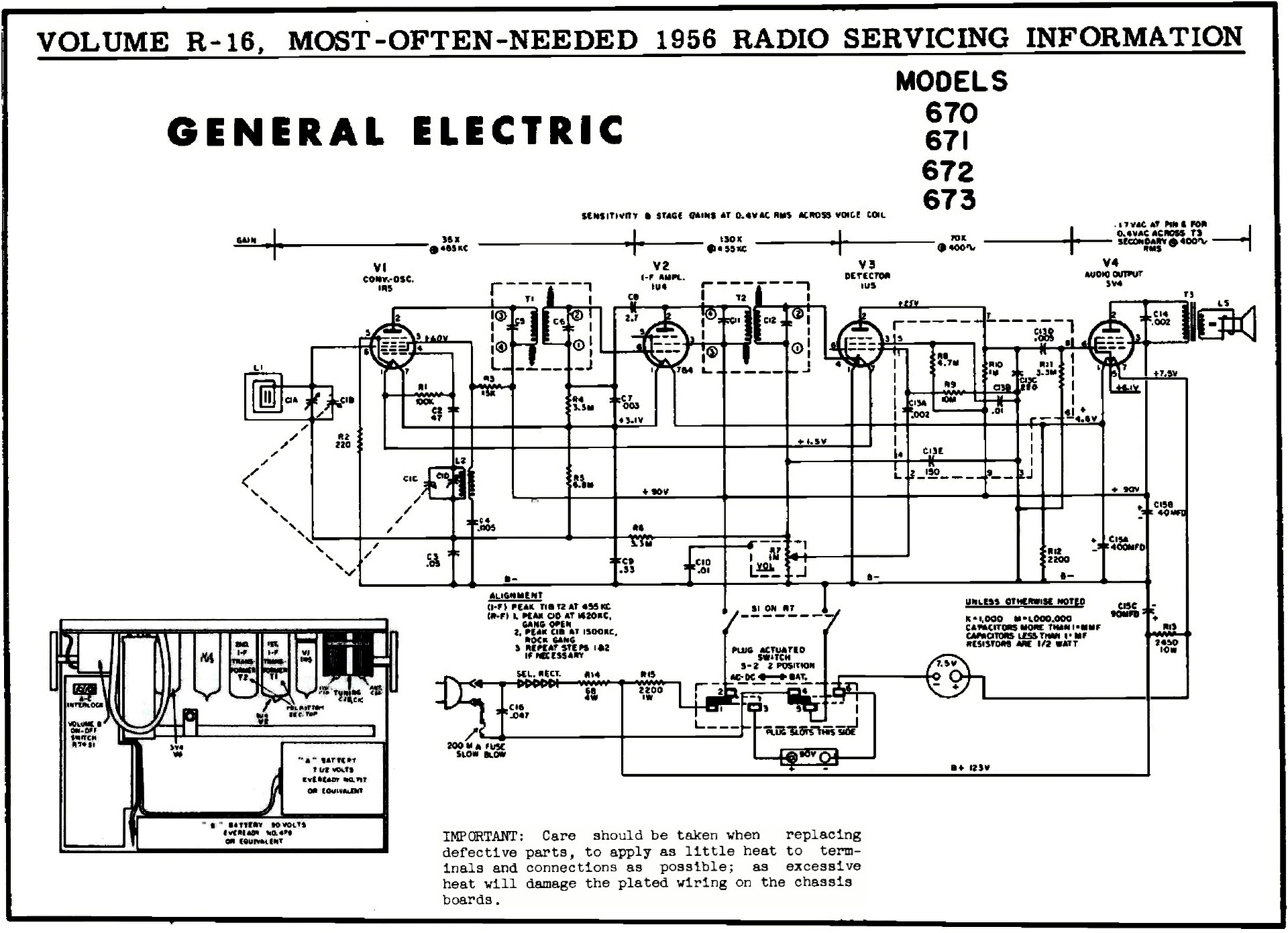
Dopo i lavori precedenti la radio si è accesa e ha funzionato, sono riuscito a sintonizzare alcune stazioni in Onde Medie, ma il suono che usciva dall'altoparlante pur avendo un livello discreto era distorto. Tentando di individuare la causa dell'audio distorto ho dissaldato, misurato e rimesso al loro posto i condensatori C3 e C9. Una volta riaccesa la radio sono rimasto molto male, adesso l'audio era alquanto peggiorato e si sentiva a malapena qualche debole segnale solo con il volume alzato al massimo. Dopo aver controllato e ricontrollato innumerevoli volte i reofori e le saldature di C3 e C9 sono passato a verificare i componenti circostanti e ho focalizzato l'attenzione sul particolare modulo integrato con nove piedini marcato GE 9PW1 situato dietro al C9. Il modulo nello schema è rappresentato da un riquadro tratteggiato che comprende varie resistenze e condensatori. Avevo notato sin dall'inizio del restauro che il modulo presentava una crepa verticale ma siccome era saldato proprio dietro a C9 ho ipotizzato che muovendo quest'ultimo dovevo aver provocato qualche ulteriore guaio all'interno del circuito integrato. Per trovare conferma del sospetto ho ricontrollato le tensioni sui piedini delle due valvole tra cui è situato il modulo e con sorpresa ho misurato 0,6 V sulla placca della V3 anziché 25V come riportato sullo schema. La tensione anodica è fornita alla 1U5 tramite la resistenza R10 da 1 MΩ contenuta nel modulo. A farla breve ho collegato una resistenza esterna da 1 MΩ 1 W tra il piedino 2 della valvola e il pin 9 del modulo, ho riacceso la radio e con gran sollievo dall'altoparlante è uscita ad alto volume la voce dell'annunciatrice di Radio Koper che trasmette a 549 kHz sulle Onde Medie. Probabilmente la resistenza da 1 MΩ interna al modulo 9PW1 era già in crisi prima del mio intervento sui condensatori (era la causa dell'audio distorto) e muovendo il componente si è interrotta del tutto. Una volta saldata sul circuito stampato la resistenza nuova il collegamento è stato ripristinato e una volta alimentata a 110 Vac la radio ha ripreso a funzionare perfettamente ricevendo con soddisfacente volume le stazioni ancora presenti nella mia zona sulle Onde Medie. IK3HIA © 2026. |
|||||||
 |
 |
 |
 |
||||
|
After opening the radio, removing the screws and cardboard covers, and freeing the two circuit boards, I found the fuse on the power supply board blown. A previous owner had likely connected the radio to the European 220 VAC voltage instead of the 110 VAC used in the US. Fortunately, the fuse did not obey Murphy's Law; the tube filaments did not burn out, so I was able to continue restoring the radio, replacing the blown fuse with a 6.3 × 32 mm 400 mA one. Also on the power supply board, I decided to preemptively replace the still-efficient but potentially dangerous selenium rectifier (link to the interesting explanation by W3HWJ in the W5RKL page). For the new rectifier, I used four 1N4004 silicon diodes connected in series to obtain approximately the same resistance and therefore the same voltage drop as the old original rectifier. Also as a precaution, I replaced all the radio's electrolytic capacitors with new ones of the same rating but with higher operating voltages. I used the old aluminum container from the original multiple capacitor, sawing it at the base with a jigsaw, patiently emptying it of its contents, and cleaning the residue with paper towels and denatured alcohol. Modern electrolytic capacitors are small, and I managed to cram a few into the old aluminum container to achieve the required capacitance. Before applying power (110 VAC via an autotransformer), I checked the continuity of the connections and found that the large wire resistor R13, which powers the tube filaments, was broken. On the schematic, R13 is rated at 2450 Ohm 10 W, and to restore it, I used three 820 Ohm 10% 5 W resistors soldered in series and hidden with pieces of the old insulating sheath (fiberglass fabric?) from the original wire resistor. Once the new R13 resistor was soldered, I checked the voltages supplied by the power supply, which were 85 V measured at pin 3 of V4 and 6.8 V measured at pin 7. The voltages were lower than they should be, but that was fine with me as they would ensure operation by putting less stress on the tubes. (Go on »). |
|||||||
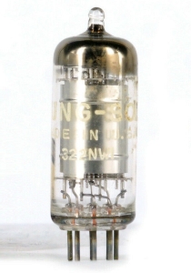 1R5 |
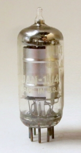 1U4 |
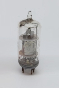 1U5 |
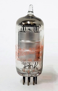 3V4 |
||||
|
After the previous works, the radio turned on and worked. I was able to tune in a few broadcasting stations, but the sound coming out of the speaker, despite having a decent level, was distorted. In an attempt to identify the cause of the distorted audio, I desoldered, measured, and re-soldered capacitors C3 and C9. Once I turned the radio back on, I was very disappointed. The audio had now deteriorated considerably, and I could barely hear a few faint signals, only at full volume. After checking and rechecking the leads and solder connections of C3 and C9 countless times, I moved on to inspect the surrounding components and focused my attention on the particular nine-pin integrated module marked GE 9PW1, located behind C9. The module in the diagram is represented by a dotted box containing various resistors and capacitors. I had noticed from the beginning of the restoration that the module had a vertical crack, but since it was soldered directly behind C9, I hypothesized that by moving the latter, I must have caused some further damage inside the integrated circuit. To confirm my suspicion, I rechecked the voltages on the pins of the two tubes between which the module is located and, to my surprise, measured 0.6 V on the V3 plate instead of the 25 V reported in the diagram. The anode voltage is supplied to the 1U5 via the 1 MΩ resistor R10 inside the module. To make a long story short, I connected an external 1 MΩ 1 W resistor between pin 2 of the tube and pin 9 of the module. I turned the radio back on, and to my great relief, the loud voice of the Radio Koper announcer, broadcasting at 549 kHz on medium waves, came out of the speaker. The 1 MΩ resistor inside the 9PW1 module was probably already failing before I fixed the capacitors (it was the cause of the distorted audio), and moving the component completely broke it. Once the new resistor was soldered to the circuit board, the connection was restored, and once powered at 110 VAC, the radio worked perfectly again, receiving the stations still available in my area on broadcasting range with satisfactory volume. IK3HIA © 2026. |
|||||||
 |
 |
 |
 |
||||
|
Back to the top of the page |
|||||||
|
|
|
Return to: IK3HIA
page
|