 |
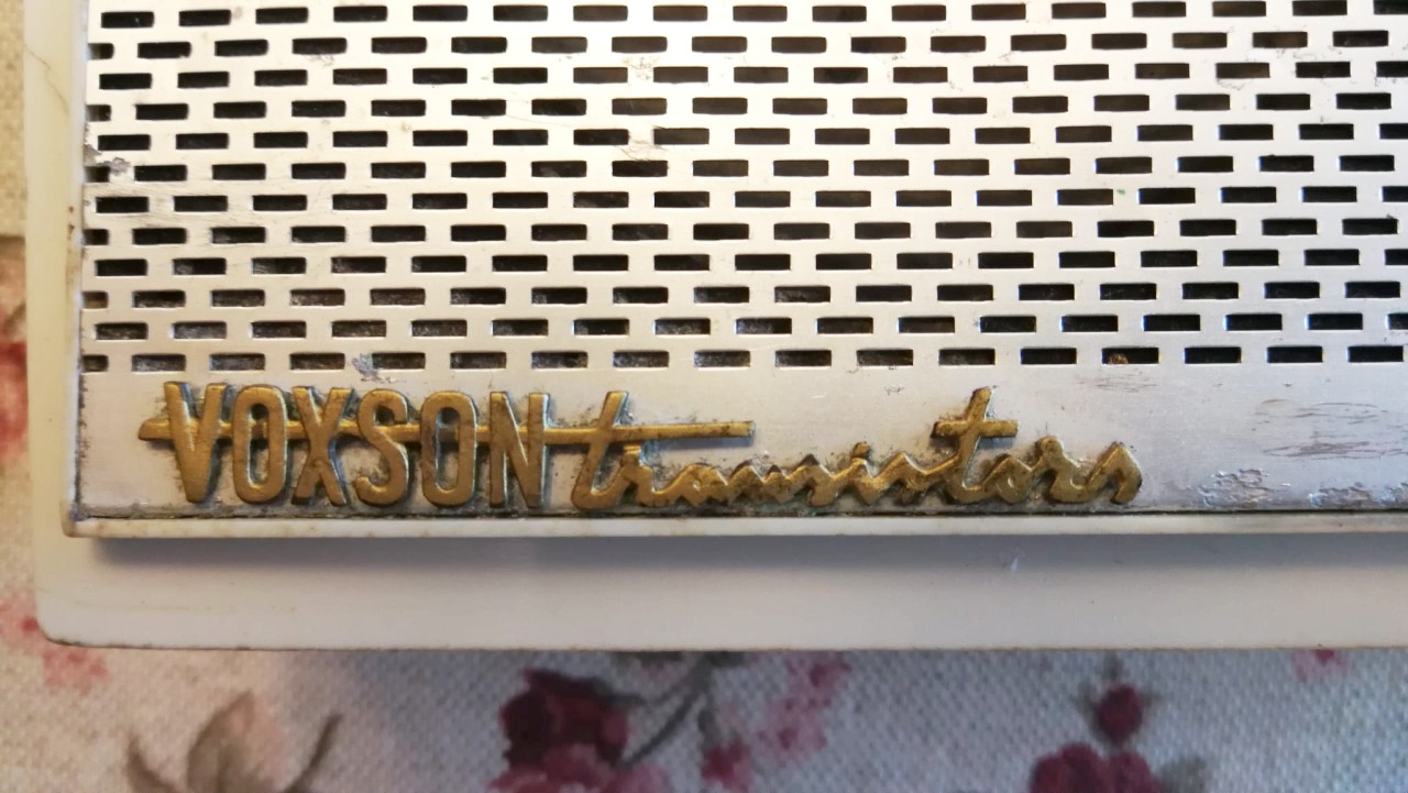
VOXSON Zephyr
3th mod. 752 Italy - 1962 |
|
|
|
VOXSON Zephyr
3th mod. 752 Italy - 1962 |
|
|
|
 |
Italiano
Restauro |
|||
|
|
|||||
 |
 |
 |
 |
||
|
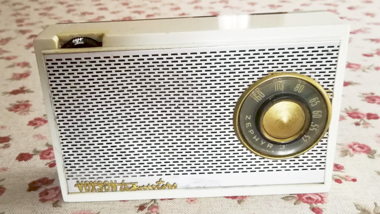
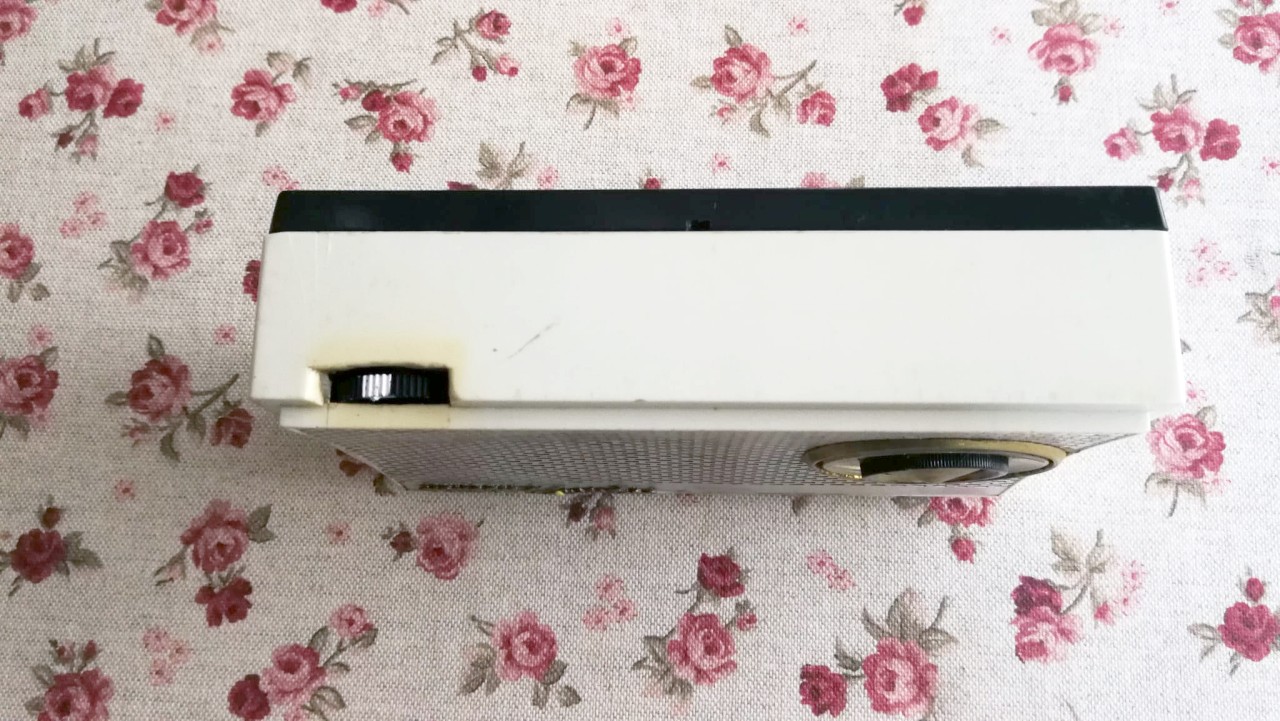
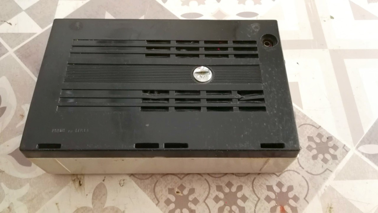
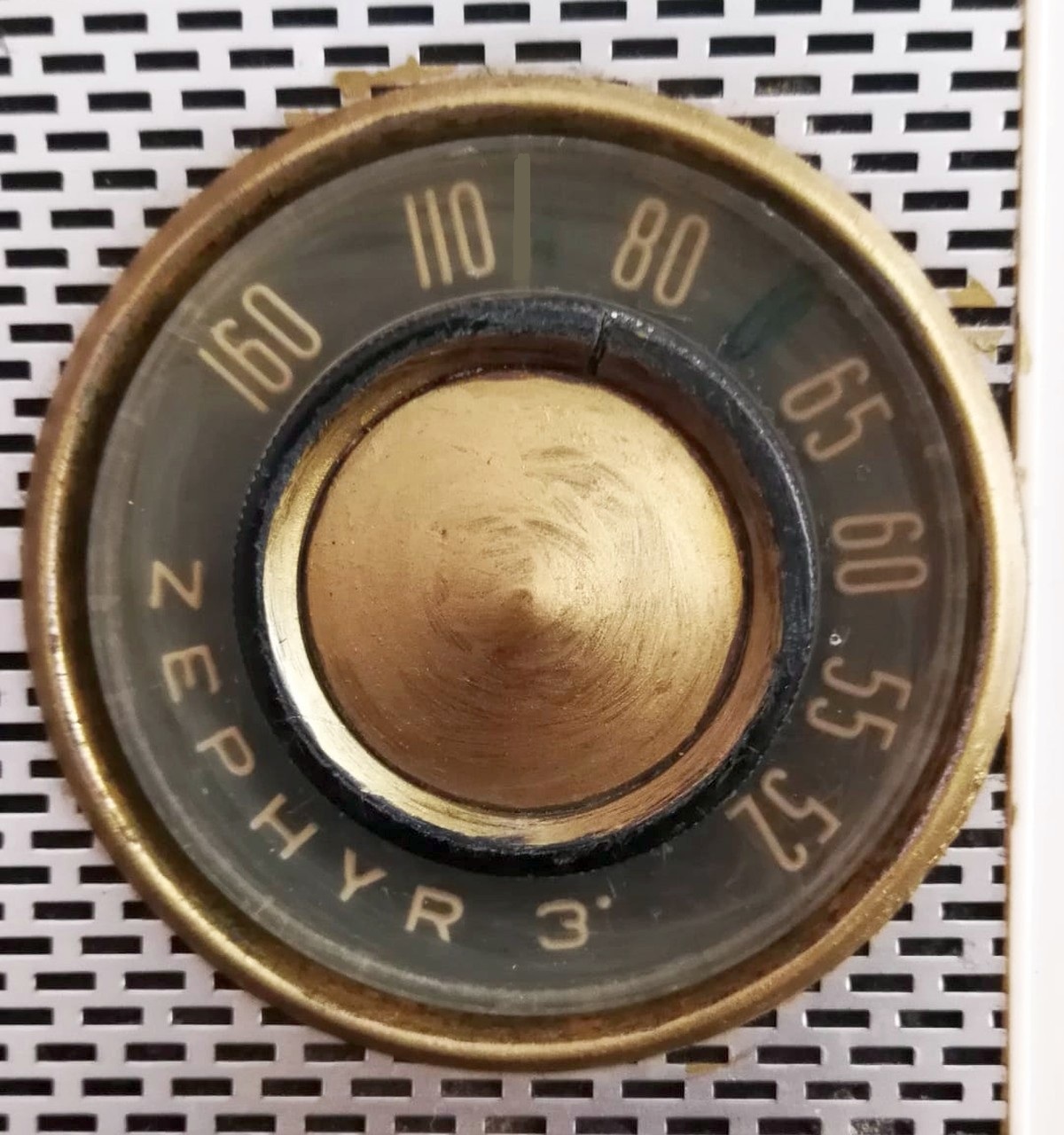
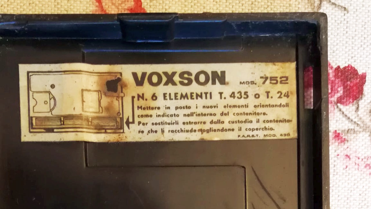
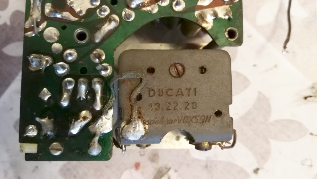
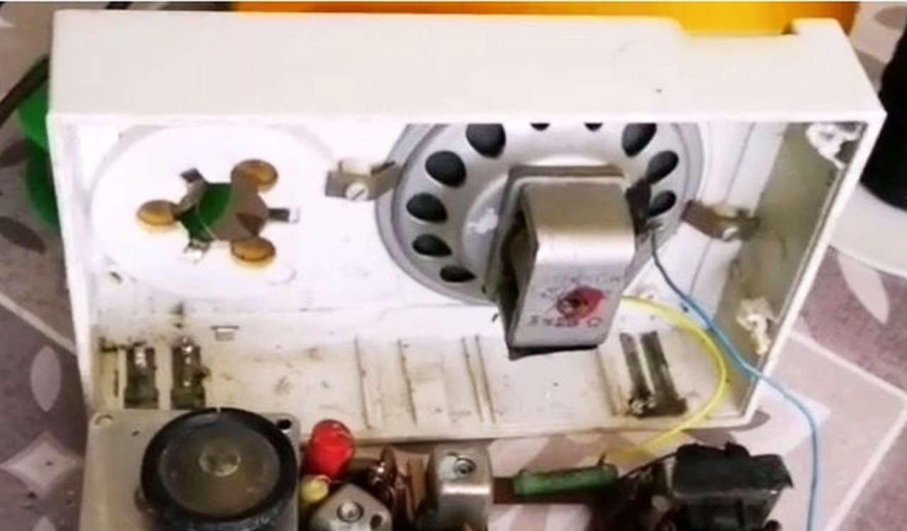
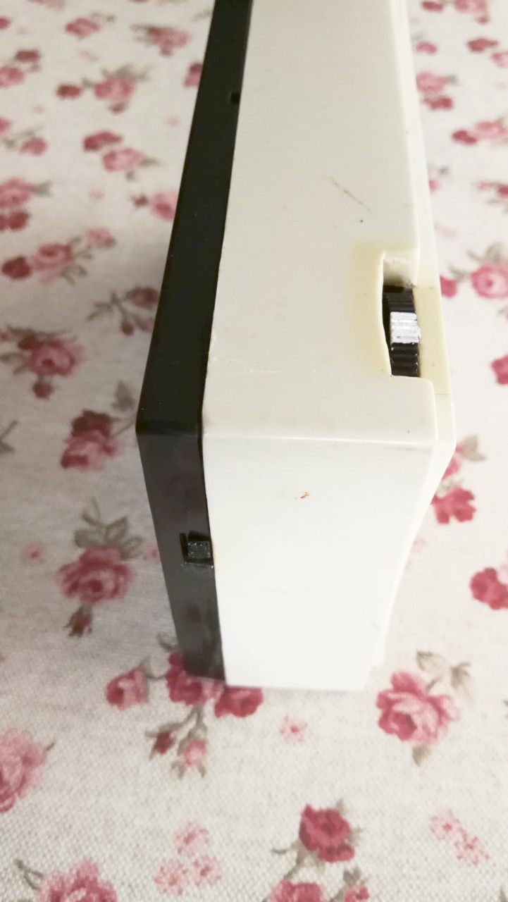
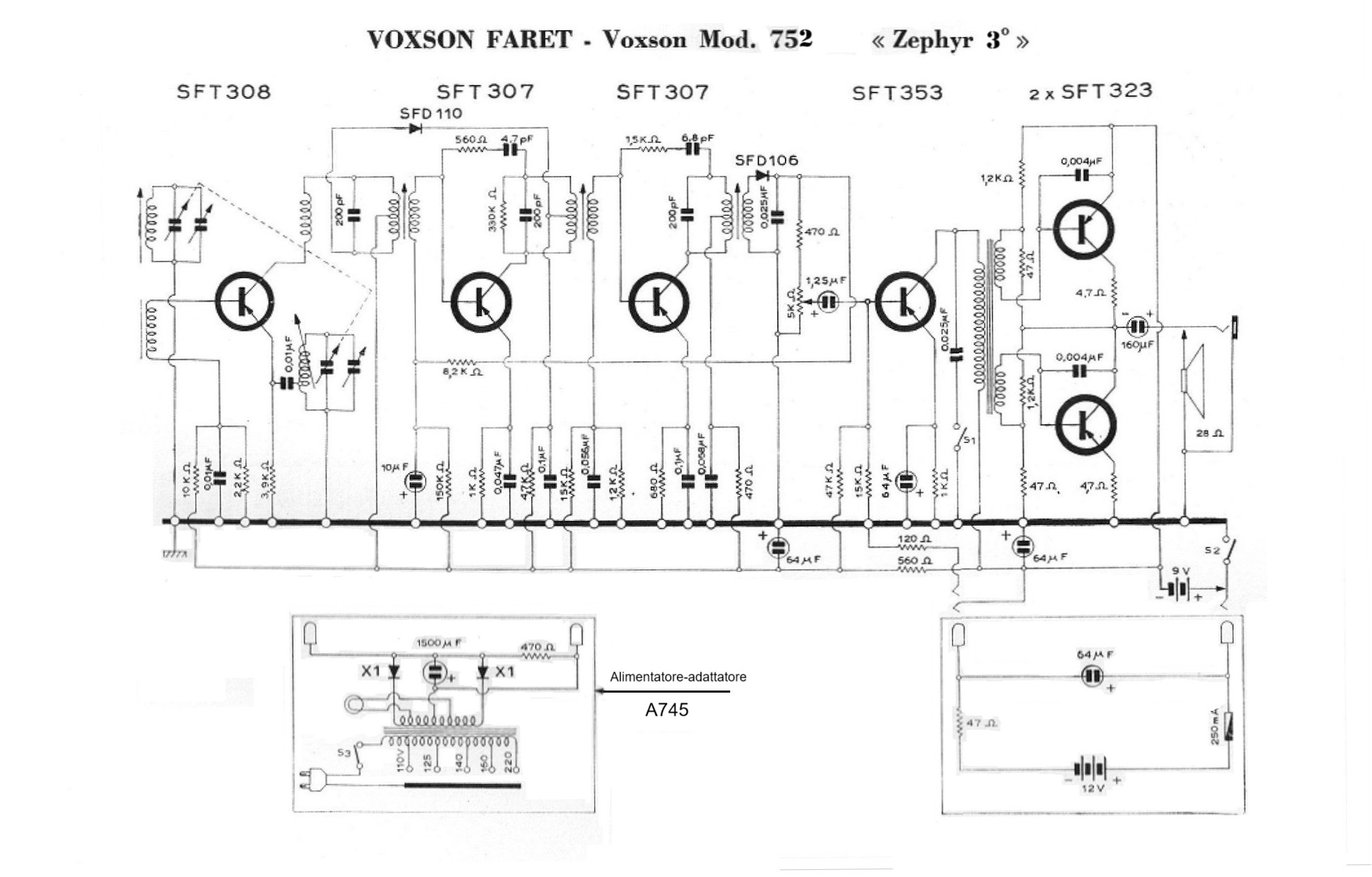
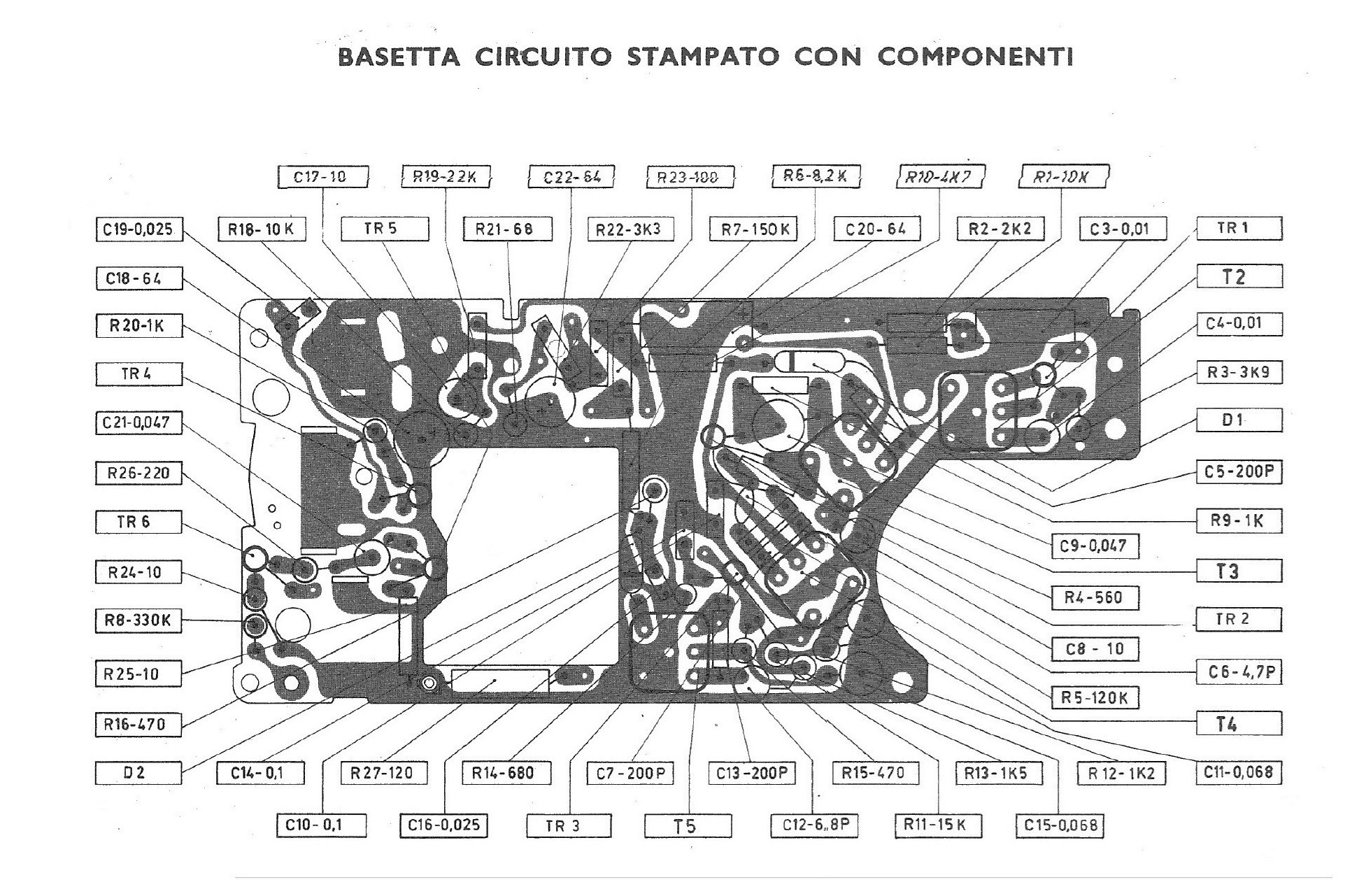
The 752 is a portable radio with a superheterodyne circuit that uses 6 germanium transistors of the SFT series (C.O.S.E.M. - Saint-Egrève - France): SFT308, SFT307, SFT307, SFT353, SFT323, SFT323 and two germanium diodes: SFD110 and SFD106. The Zephyr 3 receives Medium Waves with Intermediate Frequency at 455 kHz. The antenna is wound on a ferrite core and the tuning circuit uses a double variable capacitor with air insulation built by the Ducati company of Bologna expressly for Voxson (Special for Voxson). Depending on the components available in stock, for the same model Voxon used OC or SFT series transistors, a push-pull audio final stage with two transformers and a pair of OC72, or with a single transformer and a pair of SFT323 (very similar to AC128) in class B connected in "single ended" with a 3.1 inch and 28 Ohm impedance speaker. This is the case of the model in my possession. The cabinet is made of plastic with a perforated and anodized aluminum front where the round tuning scale is located with a knob in the middle. The volume control with its on/off switch is located on the upper left part of the cabinet. In the rear cover of the cabinet there is a jack socket for the earphone and on the left side a toggle switch allows you to insert or remove the tone control. Power can be supplied by 6 x 1.5V AA batteries (LR6 or UM3) or by the mains or even by the 12V system of a car using special power supplies/adapters. Dimensions are: 16.5 x 10 x 5 cm (WxHxD) / 6.5 x 3.9 x 2 inch. © IK3HIA 2025. |
|||||
 |
 |
 |
 |
||
|
La 752 è una radio portatile con circuito supereterodina che utilizza 6 transistor al germanio della serie SFT (C.O.S.E.M. - Saint-Egrève - France): SFT308, SFT307, SFT307, SFT353, SFT323, SFT323 e due diodi al germanio: SFD110 e SFD106. La Zephyr 3 riceve le Onde Medie con Frequenza Intermedia a 455 kHz. L'antenna è avvolta su nucleo in ferrite e il circuito di sintonia utilizza un condensatore variabile doppio con isolamento ad aria costruito dalla ditta Ducati di Bologna appositamente per la Voxson (Speciale per Voxson). A seconda dei componenti disponibili a magazzino, per lo stesso modello la Voxon utilizzava transistor della serie OC oppure SFT, uno stadio finale audio in push-pull con due trasformatori e una coppia di OC72, oppure con un solo trasformatore e una coppia di SFT323in classe B (molto simili agli AC128) collegati in "single ended" con un altoparlante da 28 Ohm di impedenza. Questo è il caso dell'esemplare in mio possesso. Il mobiletto è in plastica con frontale in alluminio forato e anodizzato dove è collocata la scala di sintonia rotonda con manopola nel mezzo. Il controllo del volume con relativo interruttore di accensione è situato sulla parte superiore sinistra del mobile. Nel coperchio posteriore del mobile è prevista una presa jack per l'auricolare e sul lato sinistro un interruttore a levetta permette di inserire o disinserire il controllo di tono. L'alimentazione può essere fornita da 6 x batterie da 1,5V tipo AA (LR6 o UM3) oppure dalla rete elettrica o anche dall'impianto a 12V di un'auto tramite appositi alimentatori/adattatori. le dimensioni sono: 16,5 x 10 x 5 cm (LxAxP) / 6.5 x 3.9 x 2 inch. © IK3HIA 2025. |
|||||
 |
 |
 |
 |
||
|
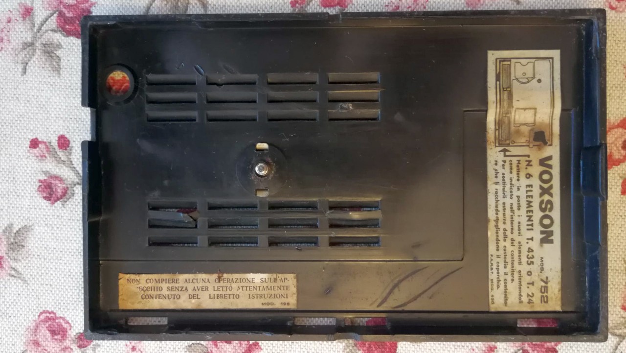
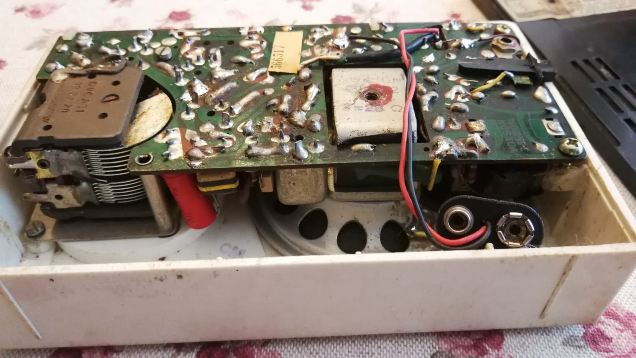
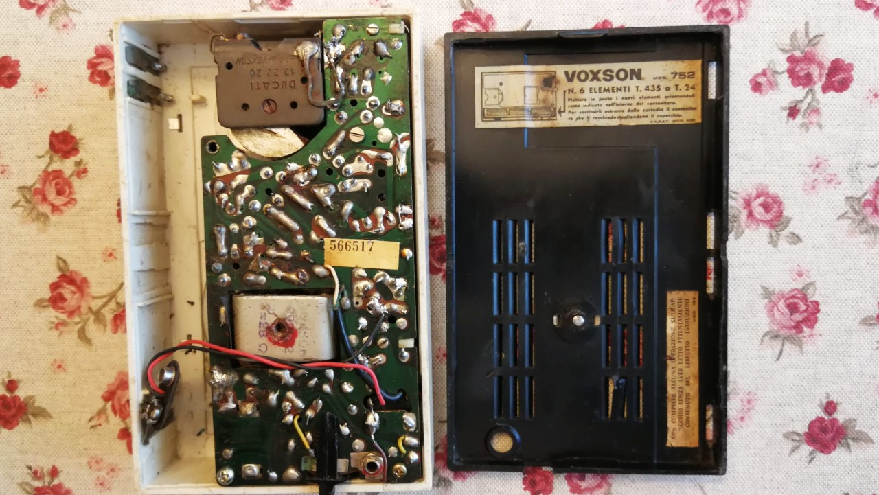
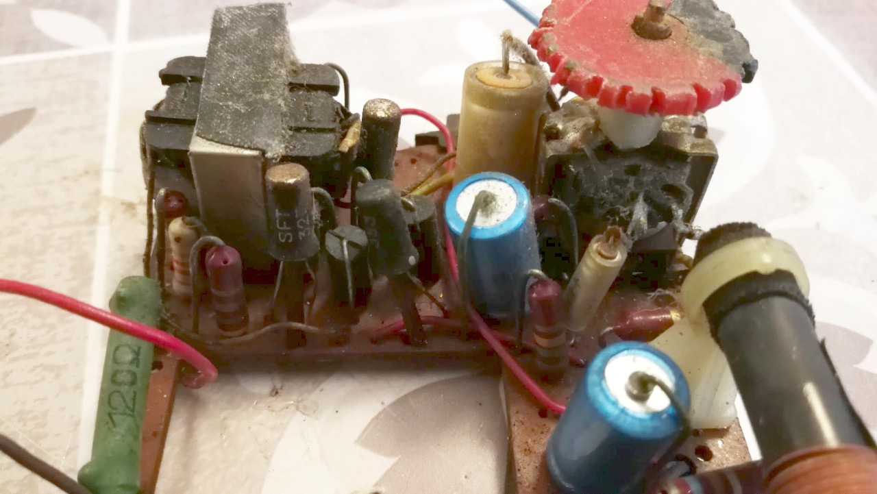
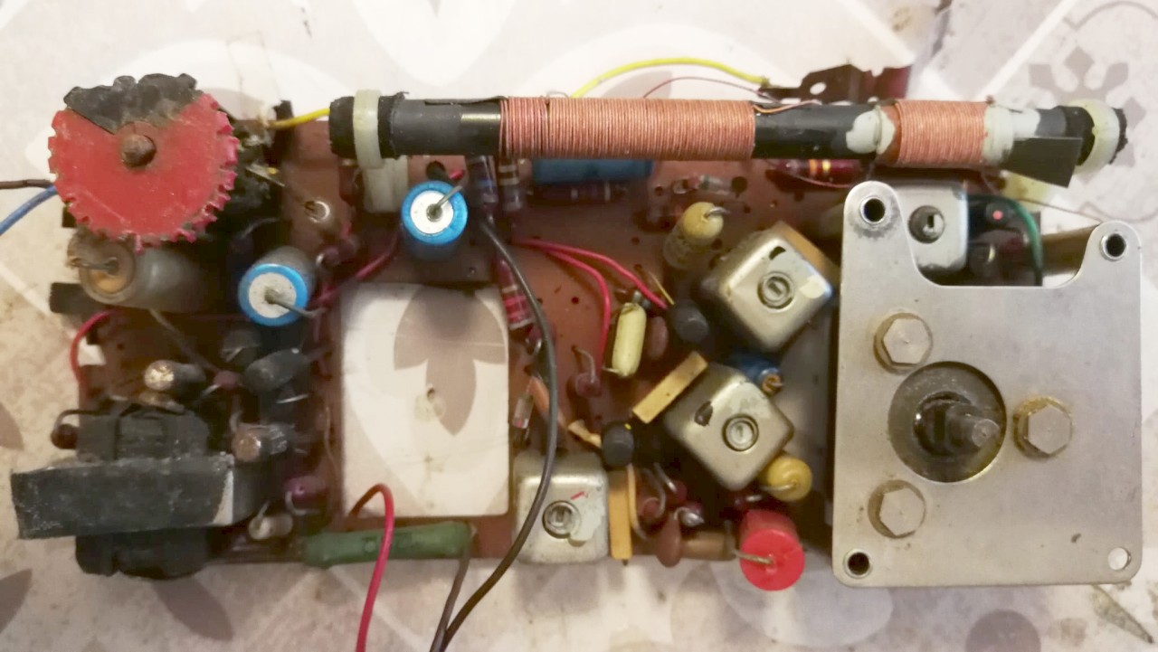
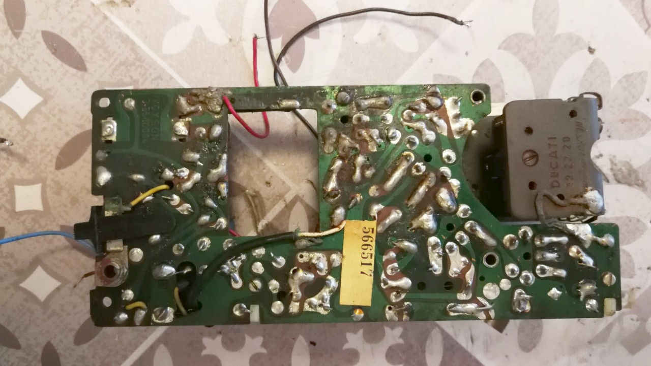
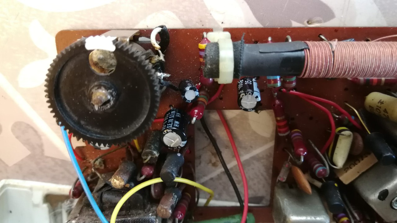
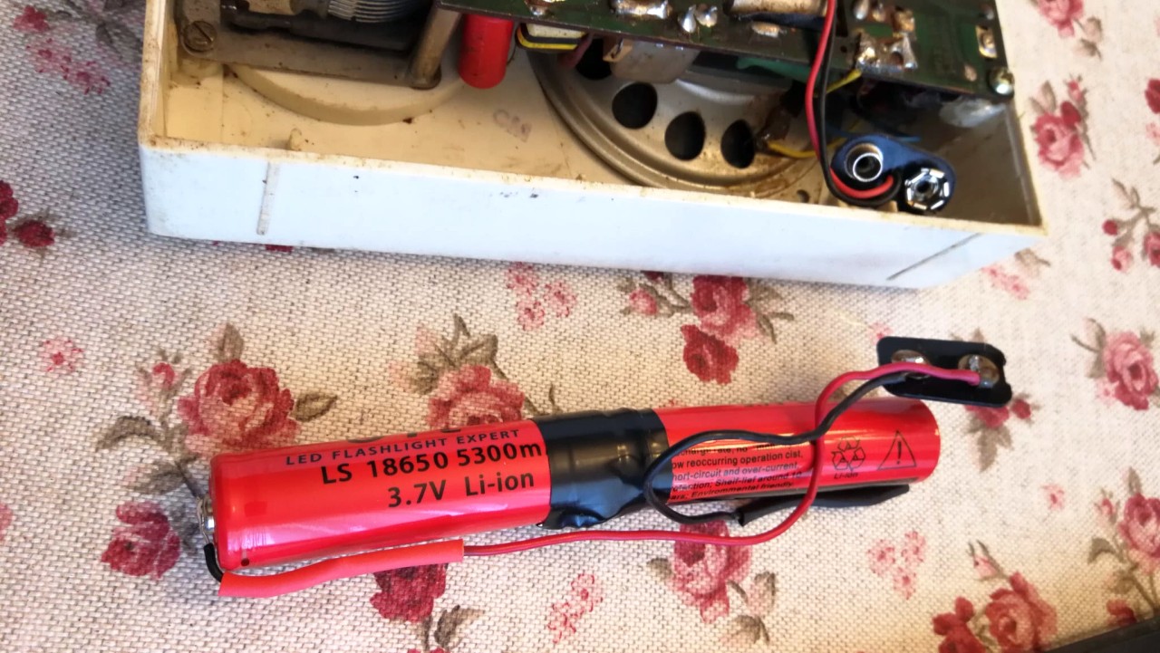
L'esemplare di Zephyr 3 visibile nelle foto mi è arrivato in pessime condizioni estetiche, con molta polvere e sporco, macchie, manopole rovinate e il condensatore variabile che traballava sui supporti in quanto le rondelle elastiche originali su cui appoggiava si erano disfatte. Ho smontato la radio e l'ho sottoposta a una pulizia generale con un pennello per asportare polvere e sporco e ho usato qualche salvietta detergente per lucidare un po' il mobile. La pulizia è proseguita con un'applicazione di spray disossidante al potenziometro e ai contatti dell'interruttore laterale del controllo del tono. Una volta terminate le pulizie ho rimpiazzato le rondelle del condensatore Ducati con altre di gomma ritagliate con un po' di pazienza e con un coltellino affilato da un tubetto flessibile di gomma del diametro giusto trovato nel mio cassetto delle meraviglie. Poi ho sostituito tutti i condensatori elettrolitici. Per i condensatori ho usato componenti nuovi tutti con tensione di isolamento maggiore rispetto agli originali. Al posto dei tre condensatori da 64 MF ne ho saldato tre da 100 MF, e al posto di quello da 160 ne ho messo uno da 200 MF, tutti da 25VL. Il condensatore da 10 MF l'ho sostituito con un altro da 10 e quello da 1,25 MF con uno nuovo da 2,2 MF da 50 VL. A questo punto ho alimentato la 752 con i 9V del mio alimentatore multi tensione e ho avuto la soddisfazione di poter subito sintonizzare alcune stazioni in Onde Medie con segnali abbastanza forti come è possibile ascoltare in questo breve video. Per rendere nuovamente la radio portatile, e visto che mancava il porta batterie originale, ho collegato in serie due batterie al litio ricaricabili tipo 18650, che a piena carica forniscono 8 V, e le ho munite di connettori ex pile 9V. Volendo terminare il lavoro in bellezza ho sostituito la disastrata manopola del volume con una ruota dentata ex giocattolo trovata nel mio solito cassetto magico, ed ecco che la Zephyr 3° è potuta entrare a far parte con successo della mia collezione di radio a transistor. © IK3HIA 2025. |
|||||
 |
 |
 |
 |
||
|
Return to top of
page
|
|||||
|
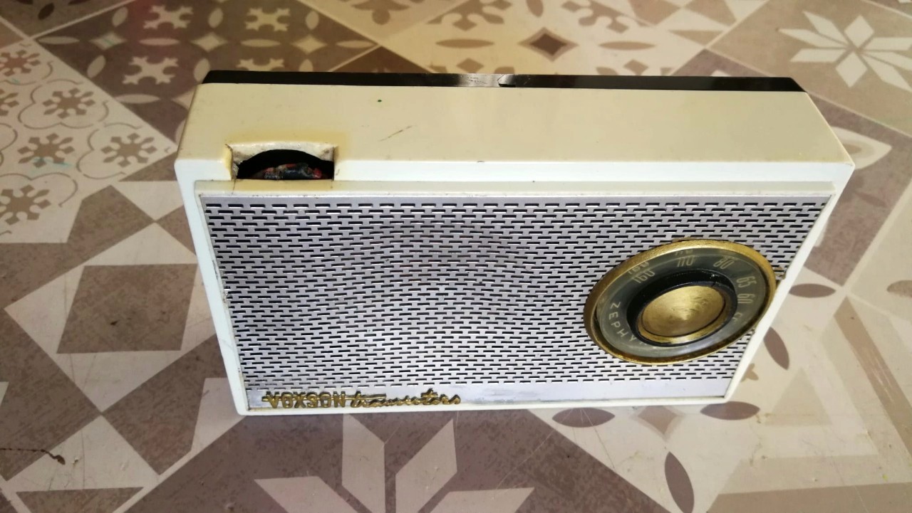
The Zephyr 3 shown in the photos arrived in terrible cosmetic condition, with lots of dust and dirt, stains, damaged knobs and the variable capacitor that was wobbling on its supports because the original spring washers it rested on had come undone. I took the radio apart and gave it a general cleaning with a brush to remove dust and dirt and used some cleaning wipes to polish the cabinet a bit. The cleaning continued with an application of deoxidizing spray to the potentiometer and the contacts of the side switch of the tone control. Once the cleaning was complete I replaced the Ducati capacitor washers with rubber ones cut with a little patience and a sharp knife from a flexible rubber tube of the right diameter found in my drawer of wonders. Then I fixed the volume knob and replaced all the electrolytic capacitors. For the capacitors I used new components all with a higher isolation voltage than the originals. In place of the three 64 MF capacitors I soldered three 100 MF ones, and in place of the 160 one I put a 200 MF one, all 25VL. I replaced the 10 MF capacitor with another 10 and the 1.25 MF one with a new 2.2 MF 50 VL one. At this point I powered the 752 with the 9V of my multi-voltage power supply and I had the satisfaction of being able to immediately tune in some Medium Wave stations with fairly strong signals as you can hear in this short video. To make the radio portable again, and since the original battery holder was missing, I connected two rechargeable lithium batteries type 18650 in series, which when fully charged provide 8 V, and I equipped them with ex-battery 9V connectors. Wanting to finish the job in style I replaced the disastrous volume knob with an ex-toy cogwheel found in my usual magic drawer, and behold, the Zephyr 3° was able to successfully become part of my collection of transistor radios. © IK3HIA 2025. |
|||||
 |
|
 |
 |
||
 |
 |
 |
 |
||
|
Return to top of
page
|
|||||
|
|
Return to: IK3HIA home page |
|
Return to: Transistor Radio |
|
Return to: Voxson radios page |